| ||
| ||
| ||
| ||
| ||
| ||
|
Intelligent Network (800/CMS/CLASS/CNAM/LIDB)
Description: OpenSS7 Project Status Applications INAP.
The IN (800/CMS/CLASS/CNAM/LIDB) product provides an IN interface library which provides a framework and applications for 800, CMS, CLAS, CNAM, LIDB services. These applications are intended to run stand-alone, or in conjunction with the switch-based applications below (OpenSwitch, Asterisk). This product focuses on the SCCP and TCAP capabilities of the OpenSS7 stack. It utilizes SUA and TUA for redunancy and reliability and supports TALI integration to Tekelec IP7 and other TALI compliant products.
A PDF version of this document is available here.
OpenSS7 CNAM Query Platform
OpenSS7 CNAM Query Platform High-Level Design
About This Manual
This is Edition 7.20141001, last updated 2014-10-25, of The OpenSS7 CNAM Query Platform High-Level Design, for Version 1.1 release 7.20141001 of the OpenSS7 package.
Executive Overview
This document provides a High-Level Design for the OpenSS7 CNAM Query Platform. The initial an primary purpose of this equipment is to provide legacy a local SS7 compatible CNAM Query Platform that interfaces with existing switching equipment, yet queries a remote CNAM database over the Internet. Because the solution attempts to avoid excessive costs for long haul graded SS7 links, the platform would benefit from using low cost commodity hardware and open source software.
The OpenSS7 Project
The OpenSS7 Project is an open source software project that has developed many protocol components within the SS7, SIGTRAN, ISDN and VoIP protocol stacks. Intellectual property rights for the OpenSS7 Project are held by OpenSS7 Corporation. All OpenSS7 Project software is eventually licensed under the GNU Affero General Public License. OpenSS7 Corporation also provide commercial licensing of OpenSS7 Project software under terms less restrictive than the AGPL.
CNAM Query Platform
OpenSS7 can provide CNAM Query Platform capabilities in a high-performance, low-cost, small-footprint platform leveraging the GNU/Linux operating system distributions and tools, and utilizing low-cost commodity hardware.
For details on platform applications, see Application Architecture, Network Architecture, Optional Application Support, and Optional Network Support.
Open Source Software
The OpenSS7 Project leverages the widespread use of GNU/Linux operation systems, distributions, and FSF tools such as ‘autoconf’ and open source software such as RPM. For example, this document was formatted for PDF, HTML, info and plain text using the GNU texinfo system, ‘autoconf’, and the TeX formatting system.
The open source model avoids proprietary lock-in and permits in-house or outsourced development. All source code is available for use and modification by the end customer. All build tools, documentation and associated resources are generally available. The availability of the source code and complete documentation eases problem resolution and can offer upgrades and fixes even in advance of client problem reports.
For details on software solutions, see Protocol Architecture, Software Architecture, Optional Protocol Support, and Optional Software Support.
Commodity Hardware
By best utilizing commodity PC or standardized CompactPCI and AdvancedTCA hardware, OpenSS7 makes available the highest performance platforms available on the market at back-to-school prices. When carrier-grade is not essential, 3GHz Pentium or Xeon class servers in hardened rack mount chassis can be used at a fraction of the cost, and yet outperform, other solutions. Where carrier-grade is necessary, embedded Linux on standardized CompactPCI and AdvanceTCA NEBS compliant chassis make for a higher cost, but more reliable alternative.
For details on hardware solutions, see Platform Architecture, Hardware Architecture, and Optional Hardware Support.
Rapid Development
The OpenSS7 Project has already developed protocol components completing the SS7 and SIGTRAN signalling stacks including MTP Level 2 and Level 3, ISUP, SCCP, TCAP; and SCTP, M2PA, M2UA, M3UA, SUA and TUA. Development of a CNAM Query Platform to meet low scale deployment requirements needs only the development of a query capability between the OpenSS7 platform and the utlimate CNAM database.
For details on scheduling, see Logistics.
An Evolving Solution
The OpenSS7 Project is evolving to support more protocol stacks including ISDN and VoIP. Support for an ever expanding capability is demonstrated by the additional options available as described in Optional Application Support, Optional Network Support, Optional Protocol Support, Optional Software Support, and Optional Hardware Support.
Conclusions
In summary, a CNAM Query Platform for small scale deployments is an excellent application of the OpenSS7 SS7 and SIGTRAN stacks and can be provided at a affordable price on short time-lines, while offering an evolution path for future deployment applications.
Brian Bidulock The OpenSS7 Project
Preface
Document Information
Abstract
This document provides a High-Level Design for the OpenSS7 CNAM Query Platform.
Objective
The objective of this document is to provide a High-Level Design for the development of a low cost, high-performance, CNAM Query Platform using OpenSS7 SS7 stack components, software, and compatible systems and hardware.
Intent
The intent of this document is to act as a High-Level Design for a project for an High-Level Design As a High-Level Design, this document discusses components and systems which are not necessarily complete. OpenSS7 Corporation is under no obligation to provide any software, system or feature listed herein.
Audience
This document is intended for a technical audience. The reader should be familiar with most ETSI, ITU-T and ANSI, Signalling System No. 7 recommendations, as well as IETF drafts and RFCs for SIGTRAN protocols. Because much of the focus of a CNAM Query Platform is on SS7 signalling, the reader should be familiar with ITU-T, ETSI and ANSI standards regarding Signalling System No. 7 as applied to Calling Name Delivery.
Revisions
Take care that you are working with a current version of this document: you will not be notified of updates. To ensure that you are working with a current version, contact the Author, or check The OpenSS7 Project website for a current version.
Version Control
$Log: cnam.texi,v $
Revision 1.1.2.4  2011-08-07 11:14:28  brian
- mostly mandriva and ubuntu build updates

Revision 1.1.2.3  2011-07-27 07:52:14  brian
- work to support Mageia/Mandriva compressed kernel modules and URPMI repo

Revision 1.1.2.2  2011-02-07 02:21:34  brian
- updated manuals

Revision 1.1.2.1  2009-06-21 10:45:50  brian
- added files to new distro
ISO 9000 Compliance
Only the TeX, texinfo, or roff source for this document is controlled. An opaque (printed or postscript) version of this document is an UNCONTROLLED VERSION.
Disclaimer
OpenSS7 Corporation disclaims all warranties with regard to this documentation including all implied warranties of merchantability, fitness for a particular purpose, non-infringement, or title; that the contents of the document are suitable for any purpose, or that the implementation of such contents will not infringe on any third party patents, copyrights, trademarks or other rights.. In no event shall OpenSS7 Corporation be liable for any direct, indirect, special or consequential damages or any damages whatsoever resulting from loss of use, data or profits, whether in an action of contract, negligence or other tortious action, arising out of or in connection with any use of this document or the performance or implementation of the contents thereof.
OpenSS7 Corporation reserves the right to revise this software and documentation for any reason, including but not limited to, conformity with standards promulgated by various agencies, utilization of advances in the state of the technical arts, or the reflection of changes in the design of any techniques, or procedures embodied, described, or referred to herein. OpenSS7 Corporation is under no obligation to provide any feature listed herein.
Document Organization
This document is organized as follows:
- Introduction
Introduction to the OpenSS7 CNAM Query Platform application.
- Application Architecture
The application requirements and architecture.
- Network Architecture
The network architecture for the application.
- System Architecture
The architecture of the OpenSS7 CNAM Query Platform system.
- Platform Architecture
The architecture of the OpenSS7 CNAM Query Platform platform.
- Protocol Architecture
The protocol architecture supporting the application.
- Software Architecture
The software architecture supporting the protocol stack and application.
- Hardware Architecture
The hardware architecture supporting the protocol stack and application.
- Logistics
Project logistics for completion of the OpenSS7 CNAM Query Platform application.
- Optional Application Support
Additional application support not directly contributing to the current objective.
- Optional Network Support
Additional network interface support not directly contributing to the current objective.
- Optional Protocol Support
Additional protocol component support not directly contributing to the current objective.
- Optional Software Support
Additional software support not directly contributing to the current objective.
- Optional Hardware Support
Additional hardware support not directly contributing to the current objective.
- Programmatic Interfaces
Programmatic interfaces to selected protocol components.
- Platform Sizing
Detailed platform sizing considerations.
- Index
Index of concepts.
1 Introduction
This document provides a High-Level Design for a platform to provide the OpenSS7 CNAM Query Platform capabilities. The primary driver for this CNAM platform is to provide a system that avoid the use of expensive graded long haul SS7 facilities. The document provides a high-level design and proposal for a production system to provide this capability.
The proposal utilizes, where possible, existing OpenSS7 SS7 and SIGTRAN stack components and provides a development plan for components that are specific to the OpenSS7 CNAM Query Platform requirements.
This document discusses the resulting software configuration that will be put in place on the production system, the platform configuration for the production system, and a lab network configuration for evaluation. Also discussed is an overview of the project management logistics for successful completion over the course of this development project.
It is intended that this document be a “living” document, that is updated over the course of this development project.
1.1 CNAM Query Platform
This project provides an OpenSS7 CNAM Query Platform that accepts and responds locally to low volume SS7 CNAM queries over traditional SS7 links, but across the CO floor, and passes the queries to a remove system using the Internet Protocol suite.
1.2 Project Drivers
The lead purpose of the OpenSS7 CNAM Query Platform is to provide a cost-effective solution to existing CNAM query services that utilize high-cost long haul graded SS7 link facilities.
1.3 Scope
Because of the focus on low cost and the need for low scale deployment, the OpenSS7 CNAM Query Platform is constructed using commodity computing platforms and PCI based hardware cards. This will initially result in a non-carrier grade system for low deployment cost. For production platforms, carrier grade options are available but are not pursued until completion of the initial phases.
1.3.1 Phases
The longer term project is broken into the following phases:
- Phase 1 1
The initial phase of the project is intended to provide the capabilities of OpenSS7 CNAM Query Platform operation for the deployment platform.
- Phase 2
The second phase of the project is to integrate the deployment platform with remote CNAM databses using the Internet Protocol suite.
- Phase 3
The third phase of the project is to perform interoperability testing and a field trial of the deployment platform.
Although some reference is made to capabilities supporting other phases, Phase 1 and Phase 2 are the focus of this document.
1.3.2 Gates
Each phase of the project consists of seven gates. The seven gates are defined as follows:
- Gate 0 — Concept
-
Gate 0 is passed when the initial concept has been elucidated and work is begun on a High-Level Design. This is an internal OpenSS7 gate.
- Gate 1 — High Level Design
-
Gate 1 is passed when the high-level design has been reviewed to the satisfaction of the consumers of the project. This is an external review gate. OpenSS7 internally passes this gate once the High-Level Design has been published and work is begun on a detailed design. 2
- Gate 2 — Detailed Design
-
Gate 2 is passed when the detailed design has been reviewed to the satisfaction of the consumers of the project and the developers on the project. This is an external as well as an internal review gate. OpenSS7 passes this gate once the Detailed Design has been published and work base begin on development and implementation of the design. 3 Passing this gate moves from the design stage to the development stage of the project.
- Gate 3 — Development and Implementation
-
Gate 3 is passed when the software and systems development and implementation to the detailed design is complete and testing has begun. This is an internal review gate. OpenSS7 internally passes this gate when software is code complete and hardware has been installed for testing.
- Gate 4 — System Test
-
Gate 4 is passed once the product implementation meets all internal ad hoc and formal conformance test suites and internal testing is complete. This is an internal review gate. OpenSS7 passes this gate internally once conformance testing is complete. Passing this gate moves from the development stage to the support stage of the project.
- Gate 5 — Acceptance Test
-
Gate 5 is passed once the product implementation has passed external Gamma client acceptance testing. This is an external review gate. OpenSS7 passes this gate internally once participation in external acceptance testing is complete.
- Gate 6 — Project Complete
-
Gate 6 is passed once all support obligations for the product implementation have been discharged. This is an internal review gate. OpenSS7 passes this gate once support agreements have terminated.
For more details on Gate scheduling for Phase 1 and Phase 2 of the project, see Schedule.
2 Application Architecture
The OpenSS7 CNAM Query Platform is intended to provide a low scale, low cost CNAM query service.
2.1 Application Background
Traditionally, Calling and Called Name Delivery service has been provided over the SS7 Signalling Network using GR-1188-CORE (formerly TR-NWT-001188). GR-1188 provides for two approaches to providing the Calling and Called names:
- ISUP Approach
-
Under the ISUP approach, the Generic Name parameter is added to the IAM (providing the calling name) and to the ACM/CPG messages (providing the called name). The calling name is provided by the originating local exchange (where the subscriber was provisioned). The name is provisioned using the line service order. The called name is provided by the terminating local exchange (again, where the subscriber was provisioned). The name is provisioned using the line service order.
- TCAP Approach
-
Under the TCAP approach, the Service Switching Point (SSP) queries a centrally located CNAM database using the called or calling number in the service key of the query and obtaining a Generic Name in response. The name is then used as though it arrived in the appropriate ISUP message and may be propagated to outgoing ISUP messages. The calling number is typically queried by the terminating exchange, whereas the called number is typically queried by the originating exchange. Names are provisioned against numbers in a CNAM database. Because there is quite an amount of other information associated wtih a local number in a LIDB (Line Information Data Base) the CNAM database and LIDB databases are normally implemented in the same database. Even though they are coexistent, the CNAM and LIDB databases have different TCAP query and response formats. While the LIDB uses a getData query, the CNAM database uses a AIN/BSDB-like service key query.
Both approaches can coexist: that is, if there is no GN in the appropriate ISUP message, a query of the CNAM database can be performed.
The traditional architecture for providing CNAM database access is to provide SS7 network connectivity between SSPs (local and terminating exchanges) requiring CNAM query capability and a centrally located CNAM/LIDB database. A number of clearing house style services have appeared which provide a single database access to an array of CNAM/LIDB databases operated by various incumbent and competitive service providers.
Typicall low-speed narrowband SS7 signalling links have the capacity of providing about 100 queries per second at 1 Erlang. Provisioned at 0.40 Erlang, 80 queries per second can be accomodated by a pair of low-speed narrowband SS7 signalling links. A rather sizeable originating and terminating exchange with 50,000 subscriber lines, each generating an average 4CCS of traffic or approximately 2 call per hour during the busy hour, generates approximately 28 transactions per second for each name. If both originating and terminating names are queried, that is as many as 56 tansactions per second. Calling and called name delivery services do not typically represent a 100% penetration in the switching center, but even given 80% penetration, that would represent about 40 queries per second, or the capacity of an entire low-speed SS7 signalling link per sizeable local switch.
Graded SS7 links are expensive. Thousands of dollars per month are required to provide the graded facility for a single SS7 signalling link. Typical incumbent query costs for CNAM queries are 0.5 cents per query. Following the 80-20 rule, 80% of the calls within a local switching exchange are intra-switch calls, and 20% are inter-switch calls. 90-95% of the calls are typically local calls and 5-10% are long distance calls. Of the 80% of the calls that are inter-switch, when both calling and called numbers are queried, an additional $0.01 per call is added for local calls for which the numbers and names belong to subscribers within the same switching center (not to mention subscribers of the same service provider). 80% of the costs associated with CNAM queries (the $0.01 per call and the capacity cost of the graded SS7 signalling links) can be avoided if a local, collocated CNAM database is provided at low cost. $0.32 per second plus 80% of the cost of the graded signalling link can be avoided. A switch with 100% penetration of both calling and called name delivery could avoid hundreds of thousands of dollars in cost per month.
2.2 Application Objectives
The objective of the CNAM application is to avoid the graded SS7 link costs and incumbent query costs associated with CNAM database queries.
- Avoid expensive graded facilities for SS7 links.
To avoid the high costs of the graded facilities required to support a pair of low-speed SS7 signalling links, by colocating an Application Gateway platform with the local exchange, the SS7 signalling links can be strung to the Application Gateway across the CO floor and the expensive graded facilities dropped. Queries to locally attached or remote databases will be performed using the Internet Protocol suite. This will avoid several thousand dollars per month in graded facility costs.
- Avoid expensive query costs on service provider’s own subscriber names and numbers.
To avoid query costs for intra-switch traffic and for inter-switch traffic where the originating and terminating switches belong to the same service provider, a locally attached, integrated or memory/disk cache database can be provided and provisioned with the service provider’s own subscriber names and numbers. This can avoid hundreds of thousands of dollars per month in incumbent or clearing house query charges.
2.3 Application Requirements
The platform has the following application requirements:
2.3.1 Phase 1 Requirements
- Direct SS7 link connectivity to one or more switches across the CO floor.
As the objective is to avoid the graded facilities necessary to support SS7 signalling links, if the CO does not have a collocated STP pair, the Application Gateway would be attached directly to the collocated switches using low-speed narrowband SS7 F-links. If the CO has a collocated STP pair, or if cost-effective access is possible via a service provider owned regional STP pair, the Application Gateway could be collocated with the STP pairs and attached via low-speed or high-speed narrowband SS7 A-links and still avoid the cost of graded facilities between the STP and a CNAM/LIDB provider.
- ANSI MTP2 conformance and interoperability (F-link and A/E-link operation).
The Application Gateway must conform to ANSI MTP Level 2 (ANSI T1.111.3/2000) for F-link and A/E-link operation, for both low-speed (56/64 kbps, ANSI T1.111.3/2000) and high-speed (1.544Mbps, ANSI T1.111.3/2000 Annex A) signalling links.
- ANSI MTP3 conformance and interoperability (F-link and A/E-link operation).
The Application Gateway must conform to ANSI MTP Level 3 (ANSI T1.111.4/2000) for F-link and A/E-link operation. The Transfer Function is not required and in all instances the Application Gateway will operate a Signalling End Point (SEP).4 This is a rather limited range of operation of the MTP Level 3 protocol layer.
- ANSI SCCP conformance and interoperability (Connectionless Protocol Class 0).
The Application Gateway must provide an SCCP layer conforming to ANSI SCCP (ANSI T1.112/2000) but only need provide Protocol Class 0 operation and does not need to provide Global Title Translation. The Application Gateway will act as an Service Control Point (SCP) in the architecture. This is a rather limited range of operation of the SCCP protocol layer.
- ANSI TCAP conformance and interoperability (Basic Query/Response).
The Application Gateway must provide a TCAP layer conforming to ANSI TCAP (ANSI T1.114/2000) but only needs to provide Operation Class 1, and simple query/response capabilities.
- CNAM conformance and interoperability.
The Application Gateway must provide CNAM query and response capability conforming to Telcordia (GR-1188-CORE), but only the TCAP method and only the CNAM Database requirements.
Phase 1 will provide an Application Gateway that can be interconnected with Service Switching Point (SSP) or Signalling Transfer Point (STP) using F-links or A/E-links, and that will provide the capabilities to receive CNAM queries and generate CNAM responses. It will provide memory/disk cacheing and integrated database capbilities.
2.3.2 Phase 2 Requirements
- SIGTRAN TUA, SR-3511 (TA1129+), SR-3389 (GDI), ONC RPC, SOAP, TCAP over SIP or other signalling transport of TCAP, or other oaffboard query capability.
The precise method selected must meet the delay expectations of the attached Service Switching Point (SSP). In the traditional arrangement, where the SS7 signalling network is used to transport queries and responses to and from the CNAM databse, the ability of the SS7 network to provide highly reliable, yet low latency tranport capabilities is expected by the querying SSPs. The query transport mechanism between the Application Gateway and a locally attached or remote back-end CNAM database must meet the same requirements.
It has been shown that TCP is unsuitable as a transport for these types of signalling applications. Random noise and transient congestion can cause excessive delays and deadline misses for a large number of queries. SCTP is a transport protocol developed by the IETF specifically for handling signalling applications such as these.
The TCAP User Adaptation Layer (TUA) for SCTP provides the ability to transport SS7 TCAP queries using SCTP. TUA provides not only idependent stream for queries avoiding head-of-line blocking issues associated with TCP, but provides network interface redundancy (multi-homing) and a redundancy model for clients and servers (active-standby, load sharing and broadcast).
UDP is less suitable than SCTP (but more suitable than TCP) for such applications. It is less suitable than SCTP, because SCTP provides for detection of lost packets and fast retransmission of lost packets and provides the ability to handle marginal levels of noise and transient congestion without losing queries or missing transaction response deadlines. It is more suitable than TCP in that if a transaction query or response is lost, it does not impact the deadlines of all other queries on the association (the so-called "head of line blocking" problem associated with TCP).
The only advantage that UDP and TCP have over SCTP is the fact that, being a recent protocol, offboard firewalls and session border controllers do not alway support SCTP.
Phase 2 will provide the Application Gateway of Phase 1 integrated with a SIGTRAN TUA, SR-3511 (TA1129+), SR-3389 (GDI), ONC RPC, SOAP, TCAP over SIP or other query capability for accessing locally attached or remote databases using Internet Protocol over local area network, wide area network or the public Internet.
2.3.3 Phase 3 Requirements
- Full integration of CNAM/TCAP and off-board query capabilities.
Phase 3 will provide a fully integrated and tested Application Gateway.
2.4 Solution Architecture
All solutions consist of a narrow-band TDM based SS7 front-end. To meet client solution objectives, however, a range of back-end architectures are possible:
- The OpenSS7 CNAM platform acts as a SIGTRAN STP and connects to a SIGTRAN Endpoint using M2PA. In this arrangement, full SS7 protocol stacks are run on both the front-end and back-end system. This arrangment is illustrated in Figure 2.1 below.
- The OpenSS7 TUA multipelxing driver.
This component provides TCAP User Adaptation Layer (TUA) Signalling Gateway capabilities to the Application Gateway.
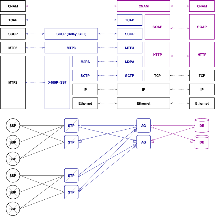
Figure 2.1. M2PA Signalling Gateway
The disadvantages of this arrangement are that it requires duplication of SS7 MTP Level 3 and SCCP on both the front-end and back-end platforms, it requires the MTP Transfer Function at the Application Gateway, it requires an SCCP Relay capability at the Application Gateway, it only supports A- and E-link connection to SSPs and B/D-link connection to STPs. In general, this is not a viable solution architecture for the CNAM Application Gateway.
- The OpenSS7 CNAM platform acts as a SIGTRAN SEP and connects to a SIGTRAN Endpoint using M2UA. In
this arrangent, only an SS7 MTP Level 2 stack is run on the front-end system and MTP Level 3, SCCP,
TCAP and the CNAM application are run on the back-end system.
This arrangment is illustrated in Figure 2.2 below.
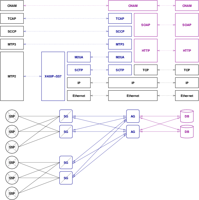
Figure 2.2. M2UA Signalling Gateway
This is a viable arrangement for the CNAM Application Gateway. It provides functional placement of the majority of the SS7 stack at the back-end. The front-end is only responsible for transporting SS7 signalling links to the back-end. It is suitable for F-link and A/E-link operation because the signalling management traffic associated with these types of signalling links is low (as compared with B/D-links or C-links).
Nevertheless, it might not be an efficient solution in that the processing power of distributed Application Gateways is not being fully utilitized. That is, the MTP Level 3, SCCP, TCAP and even part of the CNAM application can better be performed by the available processing capacity at the front-end rather that concentrated at the back-end.
- The OpenSS7 CNAM platform acts as a SIGTRAN SEP and connects to a SIGTRAN Endpoint using M3UA. In
this arrangement, only an SS7 MTP Level 3 stack is run on the front-end system and SCCP, TCAP and
the CNAM application are run on the back-end system.
This arrangment is illustrated in Figure 2.3 below.
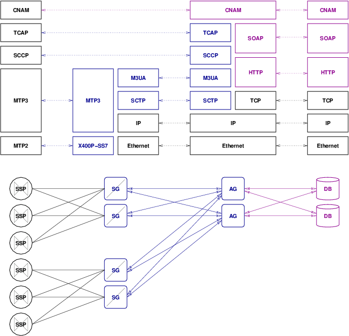
Figure 2.3. M3UA Signalling Gateway
This is a viable arrangement for the CNAM Application Gateway. It provides functional placement of the upper layer of the SS7 signalling stack at the back-end, and the lower layers at the front-end. The MTP Level 2 and 3 stack is run on the front-end system and the SCCP, TCAP and CNAM application are run on the back-end system. It is suitable for F-link and A/E-link operation because the signalling management traffic associated with these types of signalling links is low, and the MTP primitives reporting siganlling traffic management events is associated with the traffic itself.
Again, this solution might not be as efficient as others in that the processing power of distributed Application Gateways mgith be underutilized. That is, the SCCP, TCAP and even part of the CNAM application can better be performed by the available processing capacity at the front-end rather that concentrated at the back-end.
- The OpenSS7 CNAM platform acts as a SIGTRAN SEP and connects to a SIGTRAN endpoint using SUA. In
this arrangement, an SS7 MTP and SCCP stack is run on the front-end system and TCAP and the CNAM
application are run on the back-end system.
This arrangment is illustrated in Figure 2.4 below.
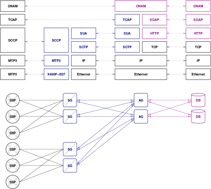
Figure 2.4. SUA Signalling Gateway
This is a viable arrangement for the CNAM Application Gateway. It provides functional placement of the TCAP layer of the SS7 signalling stack at the back-end, and the layers beneath TCAP at the front-end. It is suitable for SEP operation.
Again, this solution might not be as efficient as others in that the processing power of distributed Application Gateways mgith be underutilized. That is, TCAP and part of the CNAM application can better be performed by the available processing capacity at the front-end rather that concentrated at the back-end.
- The OpenSS7 CNAM platform acts as a SIGTRAN SEP and connects to a SIGTRAN endpoint using TUA. In
this arrangement, an SS7 MTP, SCCP and TCAP stack is run on the front-end system and only the CNAM
application is run on the back-end system.
This arrangment is illustrated in Figure 2.5 below.
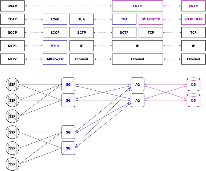
Figure 2.5. TUA Signalling Gateway
This is a viable arrangement for the CNAM Application Gateway. All SS7 signalling protocol stack layers are placed at the front-end and the application interface at the top of the TCAP stack is exported to the back-end using TUA.
This solution is more efficient than the preceding arrangements in that the processing for the entire SS7 stack is distributed across Application Gateways, better utilizing the processing capacity of those nodes and relieving the CNAM databse of this processing. This is effectively the arrangement taken by SR-3511 (TA1129+) and SR-3389 (GDI), but utilizing the TUA protocol instead and taking advantage of the capabilities of SCTP.
One disadvantage over the SUA approach is that SUA is a full RFC (RFC 3868) whereas TUA is only a draft (draft-bidulock-sigtran-tua-05.txt).
- The OpenSS7 CNAM platform acts as a SIGTRAN SEP and connects to a back-end application using
SIGTRAN TUA, SR-3511 (TA1129+), SR-3389 (GDI), ONC RPC, SOAP, TCAP over SIP or other IP-based query mechanism. This arrangement, an SS7 MTP, SCCP, TCAP stack and CNAM
application is run on the front-end system and the CNAM database itself is run on the back-end
system. In this last arrangement, CNAM query caching is possible. This arrangment is illustrated
in Figure 2.6 below.
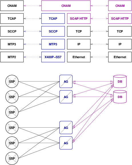
Figure 2.6. CNAM Application Gateway
A disadvantage of this approach over the TUA approach is that it is difficult to find a back-end transaction protocol that has a chance of meeting Service Switching Point (SSP) delay and reliablitiy requirements because there are few that support UDP, and fewer that support SCTP.
In all of the possible deployment arrangements, except the last two, the OpenSS7 CNAM Platform behaves as a SIGTRAN Signalling Gateway with various functional placement arragements between the front-end and back-end. These configurations are dealt with in the OpenSS7 Signalling Gateway project documentation and will not be discussed further here.
In the last two arragements, the OpenSS7 CNAM Platform has an entire SS7 stack on the platform and only communicates with the back-end via a specialized database query mechanism. These two arrangments will be the focus of this document.
2.4.1 CNAM Application Gateway
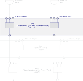
In the focal solution architecture, illustrated in Figure 2.6, the CNAM Application Gateway platform supports a complete SS7 signalling stack from MTP Level 2 throught TCAP. A CNAM application converts TCAP queries into SIGTRAN TUA, SR-3511 (TA1129+), SR-3389 (GDI), ONC RPC, SOAP, TCAP over SIP or other queries to the back-end CNAM database. Cacheing of queries is possible. Phase 1 consists of verifying the TCAP signalling stack for operation. Phase 2 consists of providing the CNAM Application for the CNAM Application Gateway. Phase 3 consists of integrating the CNAM Application on the Application Gateway with the back-end CNAM database.
The CNAM Application Gateway is build using the OpenSS7 SS7 signalling stack and associated utilities. This project does not require any additional SS7 signalling components: the CNAM portion of the queries will be processed by the CNAM Application in user-space.
This CNAM Application Gateway capability consists of a number of components:
- The OpenSS7 SS7 stack including the following components:
- The OpenSS7 Linux Fast-STREAMS subsystem.
This component supports all of the other OpenSS7 components which are based on STREAMS.
- The OpenSS7 V401P-SS7 MTP Level 2 driver for the Varion V401P card.
This component provides narrowband signalling links, both low-speed (56/64kbps) and high-speed (1.544Mbps) signalling links.
- The OpenSS7 MTP Level 3 multiplexing driver.
This component provides the Signalling End Point MTP Level 3 functions necessary to support F-links, A-links and E-links.
- The OpenSS7 SCCP multiplexing driver.
This component provides the SCCP Protocol Class 0, non-GTT capabilities required by the Application Gateway.
- THe OpenSS7 TCAP multiplexing driver or pushable module.
This component provides the TCAP Operations Class 1 capabilities required by the Application Gateway.
- The OpenSS7 TUA multiplexing driver.
This component provides TCAP User Adaptation Layer (TUA) Signalling Gateway capabilities to the Application Gateway.
- The OpenSS7 Linux Fast-STREAMS subsystem.
- A kernel resident STREAMS module that sits above the OpenSS7 TCAP protocol component, accepts TCAP queries and provides conversations and responses. This component contains the CNAM/LIDB message encoders and decoders and mapping to and from the TC interface 5 primitives of the TCAP component below. This module also implements the CNAM/LIDB query state machine and provides for rule-based, cached CNAM/LIDB query requests. This module conforms to Bellcore TR-NWT-001188 Issue 1 and Telcordia GR-1188-CORE Issue 2.
- A user-space daemon that services cache miss CNAM/LIDB requests against an external database by converting the CNAM/LIDB query into a SIGTRAN TUA, SR-3511 (TA1129+), SR-3389 (GDI), ONC RPC, SOAP, TCAP over SIP or other query to the remote database.
- User application programs used to configure and provision SS7 stack and CNAM/LIDB cache rules.
The solution architecture reuses where possible OpenSS7 SS7 stack components, drivers and hardware. The solution starts as a hardened chassis non-redundant PC-based PCI platform. A carrier grade redundant and network protection switched CompactPCI NEBS chassis is available, but would likely be excessive for this application. (See ‘CPC 388’.)
2.5 Transaction Flows
This section provides some illustrative transaction flows.6
2.5.1 Remote Database
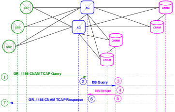
Illustrated in Figure 2.8, below, is the transaction flow that occurs when a query is directed to the Application Gateway that needs to be serviced by a remote database. A remote database is one that is distant from the Application Gateway. The intended application has the Application Gateway communicating with the remote database over the public Internet using the SIGTRAN TUA, SR-3511 (TA1129+), SR-3389 (GDI), ONC RPC, SOAP, TCAP over SIP or other protocols.
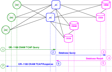
The transaction flow, illustrated in Figure 2.8, is as follows:
- The Service Switching Point (SSP) that is to perform a CNAM/LIDB dip formulates a GR-1188 CNAM TCAP Query and launches it to the CNAM subsystem for the point code associated with the CNAM/LIDB database which is locally attached via F-links. There is no GTT and routing is performed on PC and SSN only. When the Application Gateways are redundant, which of the redundant Application Gateways is selected is determined by the SLS selection made by the switch for the outgoing query.
- A query arrives at an Application Gateway the begins a transaction. The CNAM application at the AG determines, through digit analysis, that the number placed in the query is not a locally maintained number and, therefore, that it must query the remote CNAM database. It formulates a SIGTRAN TUA, SR-3511 (TA1129+), SR-3389 (GDI), ONC RPC, SOAP, TCAP over SIP or other query and launches it toward a remote CNAM database. Reduntant CNAM databases can be treated in an active-standby or load-sharing arrangement. If redundant CNAM databases are provided which database is selected depends upon the active-standby or load-sharing algorithm.
- The CNAM database receives the SIGTRAN TUA, SR-3511 (TA1129+), SR-3389 (GDI), ONC RPC, SOAP, TCAP over SIP or other query.
- The CNAM database looks up the number in the database and determines the result.
- The CNAM database formulates a SIGTRAN TUA, SR-3511 (TA1129+), SR-3389 (GDI), ONC RPC, SOAP, TCAP over SIP or other result, providing the result back to the same Application Gateway that launched the query.
- The Application Gateway correlates the SIGTRAN TUA, SR-3511 (TA1129+), SR-3389 (GDI), ONC RPC, SOAP, TCAP over SIP or other result with the SIGTRAN TUA, SR-3511 (TA1129+), SR-3389 (GDI), ONC RPC, SOAP, TCAP over SIP or other query and the SIGTRAN TUA, SR-3511 (TA1129+), SR-3389 (GDI), ONC RPC, SOAP, TCAP over SIP or other query with the TCAP Query, and formulates either a CNAM TCAP Response, or a CNAM TCAP Reject. The Application Gateway may include the ACG (Automatic Code Gapping) parameter in the response to indicate an overload condition at the AG to the Service Switching Point (SSP). The TCAP response or reject is routed to the originating PC and SSN of the query.
- The Service Switching Point (SSP) processes the response or reject and considers the optional ACG parameter to effect overload controls.
The overall transaction flow must take into consideration the transactional requirements of the Service Switching Point (SSP). Many SSPs are provisioned for a maximum number of open transactions. The provisioned maximum number of open transactions and the peak transaction rate determine the nominal response time.
For example, given a local switch with 50,000 lines each generating 4 CCS of traffic, during the busy hour, peak, with an average 200 second call, will result in 2 call attempts per line during the busy hour, for 100,000 calls per hour, or 28 calls per second. With 100% calling and called name display penetration, that ammounts to 28 transactions per second. During a busy period, there could be 60 transactions per second. With a nominal response time of 500 milliseconds, there must be a provisioned maximum number of open TCAP transactions of 30.
Nominal response times must also meet switching requirements for delay as the number must be generated between the first and second rings of the terminating line. It is not obvious that peforming a TCP based transaction to a distant CNAM database over the public internet will provide the nominal response times necessary.
2.5.2 Locally Attached Database
Illustrated in Figure 2.9, below, is the transaction flow that occurs when a query is directed to the Application Gateway that needs to be serviced by a locally attached database. A locally attached database is one that is maintained in proximity to the Application Gateway. A locally attached database could contain names and numbers for subscribers of the service provider with which the Application Gateway is collocated. The intended application has the Application Gateway communicating with the remote database over a LAN using the SIGTRAN TUA, SR-3511 (TA1129+), SR-3389 (GDI), ONC RPC, SOAP, TCAP over SIP or other protocols.
In general, with the exception of query delays concerns, the transaction flow for the locally attached database and the transaction flows for the remotely attached database are identical from the perspective of the Application Gateway, just to different databases.
The transaction flow, illustrated in Figure 2.9, is as follows:
- The SPP that is to perofrm a CNAM/LIDB dip formulates a GR-1188 CNAM TCAP Query and launches it to the CNAM subsystem for the point code associated with the CNAM/LIDB database which is locally attached via F-links. There is no GTT and routing is performed on PC and SSN only. When the Application Gateways are redundant, which of the redundant Application Gateways is selected is determined by the SLS selection made by the switch for the outgoing query.
- A query arrives at an Application Gateway that begins a transaction. The CNAM application at the Application Gateway determines, through digit analysis, that the number placed in the query is a locally maintained number and, therefore, that it must query the locallly attached CNAM database. It formulates a SIGTRAN TUA, SR-3511 (TA1129+), SR-3389 (GDI), ONC RPC, SOAP, TCAP over SIP or other query and launches it toward a locally attached CNAM database. Redundant CNAM databases can eb treated in an active-standby ro load-sharing arrangement. If redundant CNAM databases are provided, which database is selected depends upon the active-standby or load-sharing algorithm.
- The CNAM database receives the SIGTRAN TUA, SR-3511 (TA1129+), SR-3389 (GDI), ONC RPC, SOAP, TCAP over SIP or other query.
- The CNAM database looks up the number in the database and determines the result.
- The CNAM database forumlates a SIGTRAN TUA, SR-3511 (TA1129+), SR-3389 (GDI), ONC RPC, SOAP, TCAP over SIP or other result, providing the result back to the same Application Gateway that launched the query.
- The Application Gateway correlates the SIGTRAN TUA, SR-3511 (TA1129+), SR-3389 (GDI), ONC RPC, SOAP, TCAP over SIP or other result and the query with the TCAP Query, and formulates either a CNAM TCAP Response, or CNAM TCAP Reject. The Application Gateway may include the ACG (Automatic Code Gapping) parameter in the response to indicate an overload condition at the Application Gateway to the Service Switching Point (SSP). The TCAP response or reject is routed to the originating PC and SSN of the query.
- The Service Switching Point (SSP) processes the response or reject and considers the optional ACG parameter to effect SCP overload controls.
The overall transaction flow must still take into consideration the transactional requirements of the Service Switching Point (SSP). Many SSPs place limits on nominal transaction delays as well as the number of open transactions.
In particular, protocols that use TCP as a transport can have significant transaction delays introduced due to marginal amounts of noise or congestion, even for a locally attached database. It is recommdended that database protocols utilizing only UDP or SCTP transports be utilized. UDP trades missing one trasaction for delaying all transactions on a given association. SCTP provides the ability to decouple trasnactions into indepdendent streams while retaining the ability to detect packet loss and perform retransmission to avoid missing deadlines.
If SCTP were to be used, the most straightforward approach would be that of using the TCAP User Adatpation Layer (TUA) from the SIGTRAN protocol suite over SCTP as illustrated in Figure 2.5. In that configuration, TUA would provide the decoupling of transactions into independent SCTP streams for maximum reliabilty with a minimum of missed deadlines. TUA in this arrangements also directly accomodates Application Server in the active-standby, load sharing and broadcast redundancy arrangements.
SCTP makes more sense for a locally attached database than a remotely attached database. Locally attached databases can be directly connected on LAN segments that do not connect with the public Internet and do not, therefore, need firewalling. For remotely attached databases, particularly when they are attached over the public Internet, require sophisticated firewalls (e.g. Session Border Controllers), many of which do not fully support SCTP.
Therefore, UDP makes more sense for a remotely attached database. One such protocol that runs over UDP is the TA1129+ or SR-3511. These consist of placing the TCAP portion of a CNAM TCAP transaction into a UDP packet directly and passing it to the database. An application at the database translates the TCAP trasnaction to an SQL query and processes the SQL reponse into a TCAP Response which is then placed directly into a UDP packet and returned to the Application Gateway.
Other methods for placing TCAP messages in UDP packets are the TCAP over SIP method, where TCAP is converted to an XML representation of the CNAM query. The XML representation of the TCAP message is then used as the body of a SIP INVITE or INFO message. The SIP INVITE or INFO message is then sent in a UDP packet to the database.
The current likely evisions using SOAP for converting the TCAP CNAM Query into a SOAP query and then processing the SOAP response into a TCAP CNAM Response. The problem with SOAP is that the typical application transports (i.e. HTTP) use TCP as an underlying transport. TCP is unsuitable for this application due to the need to place limits on nominal response times and the number of open transactions to meet Service Switching Point (SSP) requirements.
2.5.3 Integrated Database
Illustrated in Figure 2.10, below, is the transaction flow that occurs when a query is directed to the Application Gateway that needs to be serviced by a local database. A local database is one that is maintained in proximity or conincident to the Application Gateway. A local databse could contain names and numbers from subscribers of the service provider with which the Application Gateway is collocated. The intended application has the Application Gateway communicating with an integrated databse using application programming interfaces.
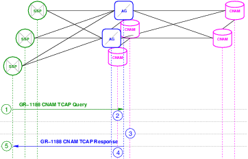
In general, with the exception that the database query is local rather than networked, the transaction flow for the integrated database and the transaction flows for the locally attached database are identical from the perspective of the Appplication Gateway, just to an integrated rather than networked database.
The transaction flow, illustrated in Figure 2.10, is as follows:
- The SPP that is to perform a CNAM/LIDB dip formulates a GR-1188-CORE CNAM TCAP Query and launches it toward teh CNAM subsystem for the point code associated with the CNAM/LIDB database which is locally attached via F-links. There is no GTT and routing is performed on PC and SSN only. When the Application Gateways are reundant, which of the redundant Application Gateways is selected is determined by the SLS selection made by the switch for the outgoing query.
- A query arrives at an Application Gateway that begins a transaction. The CNAM application at the Application Gateway determines, through digit analysis, that the number placed in the query is a locally maintained number and, therefore, that it must query the integrated CNAM database. It formulates a query and generates it using the integrated database API.
- The integrated database processes the query and returns the response.
- The response from the integrated database is used to formulate a CNAM TCAP Response or CNAM TCAP Reject. The Application gateway may include the ACG (Automatic Code Gapping) parameter in the response to indicate an overload condition at the Application Gateway to the Service Switching Point (SSP). The TCAP response or reject is routed tot he originating PC and SSN of the query.
- The Service Switching Point (SSP) processes the response or reject and considers the optional ACG parameter to effect SCP overload controls.
The overall transaction flow must still take into consideration the transactional requirements of the Service Switching Point (SSP). Many SSPs place limits on nominal transaction delays as well as the number of open transactions.
An intergrated database could also be used in the same fashion as a Disk Cache (see Memory/Disk Cache). In such a scenrio, the integrated database is populated by query misses and aging or purging of entries rather than a service order interface that would provision specific names against specific numbers. When a query is performed against the intergrated database, and the result is unkonwn for the number provided, a locally attached or remote database can be queried as well and any result obtained from those databases placed in to the intergrated database.
While some bilateral agreeemnts preclude cacheing of CNAM query results, it would be rare indeed to preclude a service provider from maintaining a databse of their own subscriber’s names and numbers, and from querying that database. Cacheing approaches to databases where the information changes very infrequently, yet the information is queried often, are quite viable. A classic example is the cacheing of HLR information at the VLR. While cacheing of LIDB entries can cause significant exposure, cacheing of CNAM results for names and numbers belonging to subscribers of the collocated service provider is effective because the service provider can purge entries from the cahce as they change.
2.5.4 Memory/Disk Cache
Illustrated in Figure 2.11, below, is the transaction flow that occurs when a query is directed to the Application Gateway that may be serviced from memory or disk cache. A memory or disk cache is a cache that maintains a limited (or unlimited) database of the results from previous queries. The cache entries can age and be deleted from the cache by age, or can be explicitly flushed. The memory or disk cache can be disabled for some numbers (e.g. numbers not belonging to the querying service provider), or disable for all numbers (i.e. in cases where cacheing is not permitted by bilateral agreements).
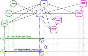
In general, with the exception that the query is directed toward a cache rather than an integrated database, the transaction flow for the cache and the transaction flows for the integrated database are identical from the perspective of the Application Gateway, just to a memory or disk cache rahter than an integrated or networked database.
The transaction flow, illustrated in Figure 2.11, is as follows:
- The SPP that is to perform a CNAM/LIDB dip formulates a GR-1188-CORE CNAM TCAP Query and launches it toward teh CNAM subsystem for the point code associated with the CNAM/LIDB database which is locally attached via F-links. There is no GTT and routing is performed on PC and SSN only. When the Application Gateways are reundant, which of the redundant Application Gateways is selected is determined by the SLS selection made by the switch for the outgoing query.
- A query arrives at an Application Gateway that begins a transaction. The CNAM application at the Application Gateway determines, through digit analysis, that the number placed in the query is a cached number and, therefore, that it must query the memory or disk cache. It formulates a query and generates it using the cache API.
- The cache processes the query and returns the response. A cache miss will result in a further step of querying an integrated, locally attached or remote database as a backing store to pull the entry into the cache. The resulting transaction flow would be as illustrated in Figure 2.10, Figure 2.9 or Figure 2.8, depending upon whether the integrated, locally attached, or remote database are used as backing store.
- The response from the cache is used to formulate a CNAM TCAP Response or CNAM TCAP Reject. The Application gateway may include the ACG (Automatic Code Gapping) parameter in the response to indicate an overload condition at the Application Gateway to the Service Switching Point (SSP). The TCAP response or reject is routed to the originating PC and SSN of the query.
- The Service Switching Point (SSP) processes the response or reject and considers the optional ACG parameter to effect SCP overload controls.
The overall transaction flow must still take into consideration the transactional requirements of the Service Switching Point (SSP). Many SSPs place limits on nominal transaction delays as well as the number of open transactions.
3 Network Architecture
Figure 3.1 illustrates the network configuration for the OpenSS7 CNAM Query Platform in a typical deployment scenario. The CNAM query platform (labelled SG in the diagram) is positioned and attached to switching equipment with intra-office SS7 F-links and communicates with the CNAM database proper using an IP network.
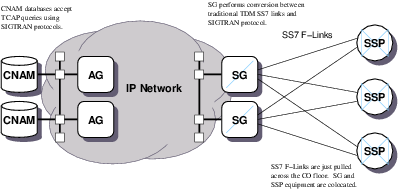
The device is attached to SSPs (switches) via V401P-SS7 or other OpenSS7 SS7 link cards, 7 terminating SS7 A-links or F-links, either 24 channels per span (T1), 56kbps or 64kbps ANSI T1.111.3 links, or 31 channels per span (E1), 64kbps Q.703 links, or full span ANSI T1.111.3 Annex B 1.544Mbps or Q.703 Annex B 2.048Mbps high-speed links, or via a signalling gateway device terminating SS7 Level 2, 3 or 4 and transporting M3UA back-haul signalling to the load device over SCTP.
On the IP network side of the device, the platform is connected on an internal LAN with multiple Ethernet segments and IP subnetworks. CNAM requests originating on Service Switching Point (SSP) within the SS7 network are accepted and responded to by the CNAM databases. Queries are converted from traditional TDM SS7 to SIGTRAN over the IP network via the Signalling Gateway.
From the viewpoint of the SS7 or SIGTRAN network, the platform acts as a Signalling Gateway for the purposes of passing CNAM queries and responses between the CNAM database and the locally attached SSPs.
Figure 3.2 illustrates functional separation between the CNAM signalling gateeway and database at the lowest functional level in the SS7 stack, MTP Level 1. This arrangement has the following characteristics:
- STP nodes may be colocated with Service Switching Point (SSP) nodes removing the need for graded SS7 transport facilities.
- MTP Level 3 need not be shared across Databases. Therefore, all TCAP queries or aborts will appear at the correct DB. Because DB nodes are not tightly coupled, they can be placed at a distance from each other.
- Functional placement does not efficiently utilize capacity: that is, both the STP nodes and the databases will be processing the entire SS7 stack, causing duplication.
Figure 3.3 illustrates functional separation between the CNAM signalling gateway and database at the lowest functional level in the SS7 stack, MTP Level 2. This arrangement has the following characteristics:
- SG nodes may be colocated with Service Switching Point (SSP) nodes removing the need for graded SS7 transport facilities.
- The greatest number of SCTP associations are required between the DB and SG: one SCTP association is required for each signalling link, so each DB requires 3 SCTP associations to each SG for the configuration in Figure 3.3.
- MTP Level 3 must be shared across databases. Therefore, some TCAP queries or aborts may appear at the wrong DB and must be routed to the other with cross-links. Because of tight coupling of the DB nodes, they must be colocated.
- Functional placement does not efficiently utilize capacity: that is, the SG nodes will be performing very little work while the DB nodes will be performing the bulk of the work (both SS7 stack processing as well as CNAM application processing).
Figure 3.4 illustrates functional separation between the CNAM signalling gateway and database at MTP Level 3. This arrangement has the following characteristics:
- MTP Level 3 must be shared across the SGs, requiring cross-links between the SGs; however, as it is expected that both SGs are colocated wth the Service Switching Point (SSP), this does not present a difficulty. DBs can be geographically dispersed.
Figure 3.5 illustrates functional separation between the CNAM signalling gateway and database at SCCP. This arrangement has the following characteristics:
Figure 3.6 illustrates functional separation between the CNAM signalling gateway and database at TCAP. This arrangement has the following characteristics:
Figure 3.7 illustrates functional separation between the CNAM signalling gateway and database at SOAP. This arrangement has the following characteristics:
3.1 SG Reference Interfaces
Figure 3.8 illustrates the HLR Reference Interfaces from 3GPP TS 24.060 Release 4.9.0 that are supported by the High Performance GSM/UMTS GPRS HLR.
| A Interface | This connects the Signalling Gateway (SG) to the Application Gateway (AG). |
| B Interface | This connects the Signalling Gateway (SG) to the Service Switching Point (SSP). |
| C Interface | This connects the Application Gateway (AG) or Signalling Gateway (SG) to the CNAM Database (DB). If the Signalling Gateway also acts as an Application Gateway, this is the interface used between the Signalling Gateway and CNAM Database. |
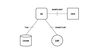
| D Interface | This connects the Signalling Gateway (SG) to the Operational Support System (OSS). |
3.1.1 A Interface
The A Interface, illustrated in Figure 3.9, below, provides the interface between the Signalling Gateway (SG) and Application Gateway (AG) elements, when these elements are not integrated together on the same platform, and consists of draft-bidulock-sigtran-tua-04.txt TCAP User Adataptation Layer (TUA) over RFC 2960/3309 SCTP over RFC 791 IP over Ethernet.
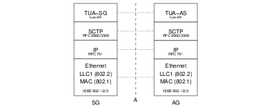
The A Interface is responsible for trasnferring CNAM TCAP queries and responses between the front-end Signalling Gateway and the back-end Application Gateway. The interface uses Stream Control Transmission Protocol (SCTP) for reliablity yet low latency transactions between the SG and AG.
- TUA
Transaction Capabilities Application Part (TCAP) User Adaptation Layer (TUA) as specified in the ITEF Internet-Draft draft-bidulock-sigtran-tua-04.txt. This protocol layer is responsible for exporting the Transaction Interface (TRI) and Trasaction Component Interface (TCI) from the Signalling Gateway (TUA-SG) to the Application Gateway (TUA-AS). The protocol layer supports SCTP as a transport for reliability and low latency as well as supporting three redundancy models: active-standby, load sharing and broadcast.
- SCTP
Stream Control Transmission Protocol (SCTP) as specified in IETF RFC 2960 and RFC 3309. SCTP is a replacement for both TCP and UDP when used with signalling applications. It is a product of the SIGTRAN (Siganalling Transport) working group of the IETF. The protocol provides multi-homing for network interface and path redudancy, preservation of record boundaries, multiple streams of data flow to prevent head-of-line blocking, fast retransmission, selective acknowledgement, orderly release, rapid association restart, rapid failure detection, and a secure 4-way handshake for starting associations.
- IP
Internet Protocol (IP) as specified in IETF RFC 791. Internet Protocol is the best-effort bastion of the Internet Engineering Task Force.
- Ethernet
Ethernet is based on the IEEE 802 and the ISO/IEC 8802 protocols. Ethernet is a derivation of the Xerox local area network protocols currently used on top of IEEE 802 lower layers.
3.1.2 B Interface
The B Interface, illustrated in Figure 3.10, below, provides the interface between the Signalling Gateway (SG) and the Service Switching Point (SSP) and consists of GR-1188-CORE Issue 2 CNAM application over ANSI T1.114/2000 TCAP over ANSI T1.112/2000 SCCP over ANSI T1.111 MTP using low- and high-speed links.
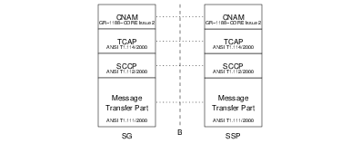
The B Interface is responsible for transferring CNAM TCAP queries and responses between the Signalling Gateway (SG) and the Service Switching Point (SSP) using directly connected SS7 links.
- CNAM
Calling Name Delivery as specified in Telcordia GR-1188-CORE Issue 2.
- TCAP
Transaction Capabilties Application Part (TCAP) as specified in ANSI T1.114/2000 and Telcordia GR-246-CORE. Based on X.219 ROSE (Remote Operation Service Execution), which is the OSI equivalent of Sun’s Open Network Computing Remote Procedure Call (ONC RPC), Transaction Capabilities Application Part (TCAP) provides the basis for applications with to engage in trasactions across the SS7 network. In this application, the mechanism is used to engage in queries and responses concerning numbers and names.
- SCCP
Signalling Connection Control Part (SCCP) as specified in ANSI T1.112/2000 and Telcordia GR-246-CORE. The Signalling Connection Control Part (SCCP) is based on X.213 CONS/CLNS and provides the equivalent of OSI network services for the SS7 network. Which would normally run over a Context and Session protocol, runs directly over the SCCP.
- MTP
Message Transfer Part (MTP) as specified in ANSI T1.111/2000 and Telcordia GR-246-CORE. The Message Transfer Part (MTP) bears little resempblence to any OSI protocol. It provides Layer 2 and partial Layer 3 services using a specialized protocol developed for Signalling System No. 7.
3.1.3 C Interface
The C Interface, illustrated in Figure 3.11, below, provides the interface between the Calling Name (CNAM) Database (DB) and the Application Gateway (AG) and consists of GR-1188-CORE Issue 2 CNAM application over W3C REC-SOAP12 Simple Object Access Protocol (SOAP) over HTTP 1.1/RFC 2616, over RFC 793 TCP, over RFC 791 IP over Ethernet.
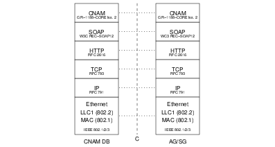
The C Interface is responsible for transferring the CNAM query and response particulars between the Application Gateway (AG) and back-end CNAM Database (DB).
- CNAM
Calling Name Delivery as specified in Telcordia GR-1188-CORE Issue 2.
- SOAP
Simple Object Access Protocol (SOAP) as specified in W3C REC-SOAP12.
- HTTP
Hypertext Transfer Protocol (HTTP) as specified in IETF RFC 2616.
- TCP
Transmission Control Protocol (TCP) as specified in IETF RFC 793 is the historical connecion-oriented protocol for the Internet Protocol (IP) suite. It suffers from may limitations that make it unsuitable for signalling applications and for which Stream Control Transmission Protocol (SCTP) was designed.
- IP
Internet Protocol (IP) as specified in IETF RFC 791. Internet Protocol is the best-effort bastion of the Internet Engineering Task Force.
- Ethernet
Ethernet is based on the IEEE 802 and the ISO/IEC 8802 protocols. Ethernet is a derivation of the Xerox local area network protocols currently used on top of IEEE 802 lower layers.
3.1.4 D Interface
The D Interface, illustrated in Figure 3.12, below, provides the interface between the Application Gateway (AG) and Signalling Gateway (SG) and the Operational Support System (OSS) and consists of ISO/IEC 9595-2/9596-2 CMISE/CMIP over RFC 1189 CMOT, over RFC 793 TCP, over RFC 791 IP over Ethernet.

The D Interface is responsible for transferring management information between the AG/SG platforms and a back-end Operational Support System.
- CMISE/CMIP
Common Management Information Service Element/Common Management Information Protocol (CMISE/CMIP) as specified in ISO/IEC 9595-2 and ISO/IEC 9596-2.
- CMOT
Common Management Information Protocol (CMIP) Over Transmission Control Protocol (TCP) (CMOT) as specified in IETF RFC 1189.
- TCP
Transmission Control Protocol (TCP) as specified in IETF RFC 793 is the historical connecion-oriented protocol for the Internet Protocol (IP) suite. It suffers from may limitations that make it unsuitable for signalling applications and for which Stream Control Transmission Protocol (SCTP) was designed.
- IP
Internet Protocol (IP) as specified in IETF RFC 791. Internet Protocol is the best-effort bastion of the Internet Engineering Task Force.
- Ethernet
Ethernet is based on the IEEE 802 and the ISO/IEC 8802 protocols. Ethernet is a derivation of the Xerox local area network protocols currently used on top of IEEE 802 lower layers.
4 System Architecture
This section details the solution system architecture. The solution system architecture consists of the computing platform and its placement within the locale installation environment.
The solution system has the following requirements:
- — 19" rack.
- — 110 VAC electrical power.
- — Commercial cooling.
- — Bantam to RJ-48c patch panel.
5 Platform Architecture
This section details the platform architecture. The solution platform architecture consists of the computing platform and associated hardware, interfaces and peripherals.
Figure 13 illustrates the solution platform rack configuration.

The solution platform consists of the following:
- — One hardened PC (5U) chassis per system.
- — One 10/100 Mbps (10/100baseT) RJ-45c Layer 2 Ethernet Switch.
5.1 Platform Capacity
The PC chassis is equipped with the following:8
- – 3GHz ix86 Pentium class Motherboard.
- – 66 MHz PCI 2.1 bus.
- – 2G DDR memory.
- – Ultra SCSI hard drive.
- – 3 x 100baseT Ethernet NICs.
- – 2 x A104c Quad E1 inteface cards.
6 Protocol Architecture
Figure 14 illustrates the protocol configuration for the OpenSS7 CNAM Query Platform system. The protocol stack uses the following OpenSS7 stack components:
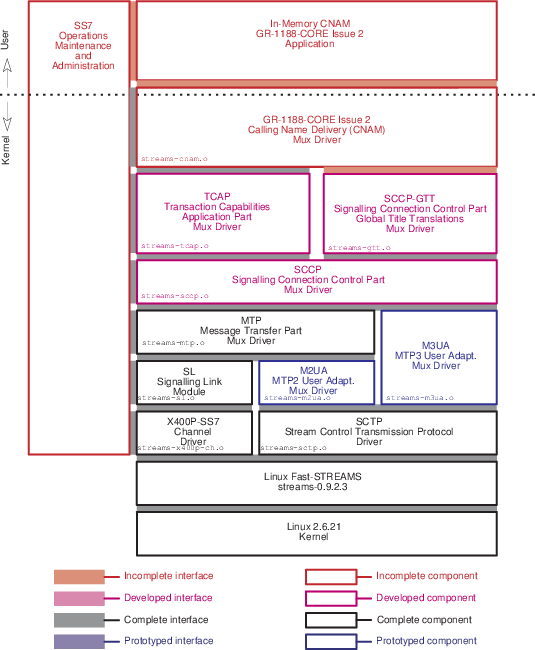
6.1 Protocol Components
The following Protocol Components are provided as part the OpenSS7 SS7 and SIGTRAN stacks:
6.1.1 In-Memory GR-1188-CORE Issue 2 CNAM Application
The High Performance HLR 3GPP TS 23.060 Rel 4. GPRS Application is responsible for providing hybrid rule-based partitioning and HLR High Performance database information to the MAP 3GPP TS 29.002 HLR driver. This is a user-space application that provides user-interface for specification of database rules and records.
The High Performance GSM/UMTS GPRS HLR Application is made up from a User-space application combined with the OpenSS7 SS7 and SIGTRAN stacks. The High Performance GSM/UMTS GPRS HLR application communicates only with the top of the SS7 stack, that is, the MAP and SCCP-GTT modules.
The High Performance GSM/UMTS GPRS HLR Application is responsible for providing data configuration instructions to the MAP and GTT modules. MAP and GTT modules accept both rule based and indexed record entries for responding to transactions and translations; any transaction or translation which neither matches a rule nor matches an indexed entry results in a transaction or translation indication to the attached High Performance GSM/UMTS GPRS HLR Application.
This protocol component is developed as part of Phase 1 of this project.
6.1.2 GR-1188-CORE Issue 2 Calling Name Delivery (CNAM) Application
The GR-1188-CORE Issue 2 Calling Name Delivery (CNAM) Application is responsible for accepting CNAM queries from the front-end attached SSPs and turning those requests into database queries to the CNAM database and propagating the response. This is a straightforward application that converts between SIGTRAN TUA, SR-3511 (TA1129+), SR-3389 (GDI), ONC RPC, SOAP, TCAP over SIP or other queries and responses and CNAM TCAP queries and responses using the published Transaction Component Interface (TCI).
The GR-1188-CORE Issue 2 Calling Name Delivery (CNAM) module is responsible for responding to SSP transactions originating from the TCAP module beneath and is responsible for generating outgoing SSP responses to the TCAP module beneath. To perform its function, the CNAM platformindexes all information based on the telephone number, including dynamic (state) and provisioned (subscriber) information. For performance in both a testing and production environment, the module provides three levels of database partitioning and caching:
- Rules
Rules can be provided that is used to determine provisioned information based on components of the Digits. These rules can be used to generate a rather large simulated database without maintaining or accessing large database record areas. The rule base provides a simulated partitioned database. Each rule refers to a template or partial template of provisioned data.
- Templates
Templates can be provided that specify a profile of provisioned information for a class of indexes (Digits). Templates provide a compact local in-kernel cache of templates. Indexes reference templates rather than complete records.
- Records
Records can be provided that specify the provisioned information for the specific index (Digits). Records provide a local in-kernel cache of specified records. Records are unique for each index.
- Transactions
The application can be queried by indicating the index Digits and the module awaits a response containing the provisioned information. Transactions provide access to an external database.
This protocol component is developed as part of Phase 1 of this project.
6.1.3 SS7 Stack Manager
The SS7 stack manager is responsible for configuration of the SS7 stack, maintenance, statistics collection, operational measurements, management events and controls, log and alarm generation. This is daemon process that is typically customized to meet a specific application.
This is an existing component of the OpenSS7 stack that is extended to include the HLR components developed above and the CNAM component developed below.
6.1.4 GR-1188-CORE Issue 2 Calling Name Delivery (CNAM) Driver
The GR-1188-CORE Issue 2 Calling Name Delivery (CNAM) Driver is responsible for accepting CNAM queries from the TCAP and TUA streams linked below as well as performing any necessary Global Title Translations (GTT) for the SCCP GTT control streams linked below. The driver contains an in-kernel-memory CNAM database. The in-memory database is hybrid rule-based an Digit indexed record-based.
The CNAM driver supports GR-1188-CORE Issue 2. This protocol component is developed as part of Phase 1 of this project.
6.1.5 Transaction Capabilities Application Part (TCAP) Driver
The transaction capabilities application part driver performs the essential transaction functions of the SS7 signalling stack. SCCP or SUA streams are linked under the driver and the driver provides the functions of a TCAP SSP or SCP, MSC or HLR, SMSC and other TCAP nodes. Transaction Capabilities Application Part streams bound to INAP, CNAM or LNP TCAP-SAPs are accessed by the transaction application using the Transaction Component Interface (TCI).
The TCAP driver supports all CCITT/ITU-T versions (Blue Book forward), ETSI and ANSI versions (1992 forward), including operation classes 1 through 5. The TCAP driver provides a specialized TR and TC interface to its users and accepts an X/Open NPI Revision 2.0 interface from beneath. In addition, a TPI Revision 2.0 user interface supporting an X/Open XNS 5.2 mOSI XTI library interface is provided.
The TCAP driver is a STREAMS driver that runs in the Linux kernel for maximum performance. The primary scale limiting characteristic of the TCAP driver is the number of simultaneous open transactions. Each open transaction requires a number of timers, state information and dynamic transaction information such as addressing. Transaction Identifier indexed hash tables must be appropriately sized and the mean and maximum simultaneous open transactions should be known for proper sizing.
The Transaction Capabilities Application Part (TCAP) STREAMS module is responsible for providing TCAP services on top of a Signalling Connection Control Part (SCCP) or SCCP-User Adaptation Layer (SUA) stream. In addition, it is possible to use an ISO/OSI Network Service Provider to provide the network services to TCAP.
The OpenSS7 TCAP component has message encoding and decoding for ITU-T/ETSI Application Context TCAP and ANSI Private TCAP. Interfaces provided to TCAP users include an XTI/mOSI capable TPI Version 2.0 interface, a Transaction Interface (TRI) as described in ITU-T Q.791, and a Component Interface (TCI) as also described in ITU-T Q.791. The ITU-T Q.791 TR and TC interfaces are support Java JTCAP.
Of these interfaces, the Transaction Interface (TRI) and Component Interface (TCI) are most efficient. This is because it is not necessary to open a new stream for each transaction as is the case with the TPI interface and the XTI/mOSI.
The OpenSS7 TCAP module supports all Operations Classes.
A SIGTRAN TCAP-User Adaptation Layer (TUA) or OpenSS7 STREAMS over SCTP multiplexing driver can be used between the TCAP and the TCAP-User to export the TCAP/TCAP-User interface between a provider and user host.
Signalling Connection Control Part (SCCP) streams are linked beneath the TCAP module to provide SCCP services to TCAP. Alternately, a SIGTRAN SCCP-User Adaptation Layer (SUA) or OpenSS7 STREAMS over SCTP stream may be linked.
The OpenSS7 TCAP module contains all the necessary state machines, timers, transaction error handling and component error handling as required by the ITU-T, ETSI and ANSI specifications.
This is an existing OpenSS7 SS7 stack component; for documentation, see: tcap(4). Phase 1 activities for TCAP include integration testing with the CNAM components.
6.1.6 Signalling Connection Control Part (SCCP) Driver
The signalling connection control part driver performs the essential transport functions of the SS7 signalling stack. Message Transfer Part or MTP3 User Adaptation Layer streams are linked under the driver and the driver provides the functions of a SCCP endpoint or relay with full global title translations. Signalling Connection Control Part streams bound to TCAP SCCP-SAPs are linked under the TCAP driver to form a complete SS7 stack in support of call transactions.
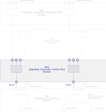
The SCCP driver supports all CCITT/ITU-T versions (Blue Book forward), ETSI and ANSI versions (1992 forward), including both connectionless and connection-oriented protocol classes 0 through 3. The SCCP driver provides an extended NPI Revision 2.0 interface to its users and accepts an NPI Version 2.0 (Connectionless) MTP interface from beneath or a specialized OpenSS7 MTPI interface. In addition, a TPI Revision 2.0 user interface supporting an X/Open XNS 5.2 XTI library interface is provided.
The SCCP driver also provide GTT streams for servicing Global Title Translations requests. These streams can be used by a user-space program for servicing GTT requests from a local or remote database, or can have specialized STREAMS modules pushed to perform rule-based GTT in the operating system kernel.
The SCCP driver is a STREAMS driver that runs in the Linux kernel for maximum performance.
The Signalling Connection Control Part (SCCP) STREAMS module is responsible for providing SCCP services on top of a Message Transfer Part (MTP) Level 3 (MTP3) or MTP3-User Adaptation Layer (M3UA) stream. In addition, it is possible to use an ISO/OSI connectionless Network Service Provider to provide the network services to SCCP.
The OpenSS7 SCCP component has message encoding and decoding for ITU-T/ETSI and ANSI SCCP. Interfaces provided to SCCP users include an XTI/OSI capable TPI Revision 2.0 interface, an NPI Revision 2.0 interface, and an SCCP-specific interface.
The OpenSS7 SCCP module supports all Protocol Classes.
This is an existing OpenSS7 SS7 stack component; for documentation, see: sccp(4). Phase 1 activities for SCCP include integration testing with the CNAM components.
6.1.6.1 Global Title Translations (GTT)
The Signalling Connection Control Part (SCCP) Global Title Translations (GTT) module is responsible for responding to SCCP-GTT translations originating from the SCCP module beneath and is responsible for generating outgoing SCCP-GTT translations to the SCCP module beneath. To perform its function, the SCCP-GTT indexes all information based on the SCCP Address, including dynamic (state) and provisioned (result) information. For performance in both a testing and production environment, the module provides three levels of database partitioning and caching:
- Rules
Rules can be provided that are used to determine provisioned information based on components of the index (GT). These rules can be used to generate a rather large simulated database without maintaining or accessing large database record areas. The rule base provides a simulated partitioned database. Each rule refers to a template or partial template of provisioned data.
- Templates
Templates can be provided that specify a profile of provisioned information for a class of indexes (GT). Templates provide a compact local in-kernel cache of templates. Indexes reference templates rather than complete records.
- Records
Records can be provided that specify the provisioned information for the specific index (GT). Records provide a local in-kernel cache of specified records. Records are unique for each index.
- Translations
The application can be queried by indicating the index (GT) and the module awaits a response containing the provisioned information. Translations provide access to an external database or algorithm.
For the High Performance GSM/UMTS GPRS HLR application, messages can be routed on Translation Type or on the basis of the Subsystem Number alone, resulting in a simple rule provided to the SCCP-GTT. If the High Performance GSM/UMTS GPRS HLR application is not expected to perform in any other role, the High Performance GSM/UMTS GPRS HLR application can bind as the "Default Destination" for all SCCP Unitdata messages, obviating the need for GTT.
This is an existing OpenSS7 SS7 stack component; for documentation, see: sccp(4). Phase 1 activities for SCCP include integration testing with the CNAM components.
6.1.7 Message Transfer Part (MTP) Driver
The message transfer part driver performs the essential network functions of the SS7 signalling stack. M2UA streams (see below) may be linked under the driver and the driver provides the functions of a Signalling End Point (SEP) or Signalling Transfer Point (STP). 9
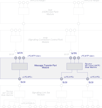
The MTP driver supports all CCITT/ITU-T versions (Blue Book forward), ETSI and ANSI versions (1992 forward), including full transfer function. The MTP driver provides a specialized MTP interface to its users, in addition to an NPI Revision 2.0 connectionless interface. A TPI Revision 2.0 (connectionless) user interface support X/Open XNS 5.2 XTI library functions is also provided.
The MTP driver is a STREAMS driver that runs in the Linux kernel for maximum performance.
The Message Transfer Part (MTP) Level 3 (MTP3) module is responsible for providing MTP services to its users.
The Message Transfer Part (MTP) Level 2 (MTP2) module is responsible for providing MTP services to its users.
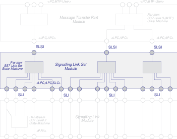
These are an existing OpenSS7 SS7 stack components; for documentation, see: mtp(4). Phase 1 activities for MTP3 and MTP2 include integration testing with the CNAM components.
6.1.8 MTP Level 3 User Adaptation Layer (M3UA) Driver
The M3UA driver provides the HLR with the ability to act as an M3UA AS (Application Server) in conjunction with an M3UA SG (Signalling Gateway). In this project, the SG function is performed by existing lab equipment. The M3UA driver accepts the transport of the MTP to MTP-User interface from the SG to the HLR. The M3UA driver links SCTP driver streams underneath it to provide the transport services for exporting the MTP-User interface. The M3UA driver provides the same interface to its users as the OpenSS7 MTP.
The M3UA driver is a STREAMS driver that runs in the Linux kernel for maximum performance.
This is an existing OpenSS7 SIGTRAN stack component; for documentation, see: m3ua(4). Phase 1 activities for M3UA include integration testing with the CNAM components.
6.1.9 Signalling Link (SL) Module
The signalling link module performs HDLC and SS7 Message Transfer Part Level 2 (Link) functions on a raw communications channel, such as that provided by the X400P-SS7 driver and the E400P-SS7 card. This module converts between the channel media stream (raw octet stream) and an SS7 signalling link signalling stream. These streams comprise SS7 signalling links and are linked under the MTP driver.
The SL module supports CCITT/ITU-T versions (Blue Book forward), ETSI and ANSI versions (1992 forward), including Q.703 and Q.703 Annex B (HSL) operation. TTC JQ.703 (1994) is also supported. The SL module provides a specialized SL interface to its users, in addition to an NCR Comten CDI Revision 2.0 Style 2 connectionless interface.
The SL module is a STREAMS module that runs in the Linux kernel for maximum performance.
The Signalling Link (SL) module is responsible for providing SL services to its users.
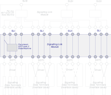
This is an existing OpenSS7 SS7 stack component; for documentation, see: sl(4). Phase 1 activities for MTP2 include integration testing with the CNAM components.
6.1.10 Signalling Data Terminal (SDT) Module
The signalling data terminal module performs HDLC and lower level SS7 Message Transfer Part Level 2 (Link) functions including DAEDR, DAEDT, AERM, SUERM and SU Compression/Repetition on a raw communications channel or span, such as that provided by OpenSS7 Channel Drivers. This module converts between the raw channel media stream (raw octet stream) and an SS7 signalling data terminal stream. These streams comprise SS7 signalling data terminals and are pushed beneath the SL module.
The SDT module supports CCITT/ITU-T version (Blue Book forward), ETSI and ANSI versions (1992 forward), including Q.703 and Q.703 Annex B (HSL) operation. TTC JQ.703 (1994) is also supported. The SDT module provides a specialized SDT interface to its users, in addition to an NCR Comten CDI Revision 2.0 Style 2 connectionless interface.
The Signalling Data Terminal (SDT) module is responsible for providing SDT services to its users.
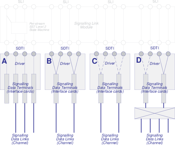
This is an existing OpenSS7 SS7 stack component; for documentation, see: sdt(4). Phase 1 activities for MTP2 include integration testing with the CNAM components.
6.1.11 Stream Control Transmission Protocol (SCTP) Driver
OpenSS7 has two implementations (STREAMS and Linux Sockets) that provide support for this new transport protocol and provide transport for SIGTRAN and other protocols. The STREAMS SCTP implementation provides an NPI Revision 2.0 and TPI Revision 2.0 interface to its users. Also supported is an X/Open XNS 5.2 XTI library. The Linux Native SCTP implementation provides a Sockets interface.
This is an existing OpenSS7 SIGTRAN stack component; for documentation, see: sctp(4). Phase 1 activities for SCTP include integration testing with the CNAM components.
7 Software Architecture
This chapter details the software configuration of OpenSS7 solutions. Open SS7 stack software is based on the STREAMS facility running on the Linux Operating System. This provides for use of the Linux Operating System while maintaining portability and consistency with major UNIX operating systems that provide an SVR 4.2 ES/MP STREAMS facility.
7.1 Linux Operating System
The OpenSS7 STREAMS releases and stacks currently support the 2.4, 2.6 and 3.x Linux Kernel. A Linux kernel version greater than or equal to 2.4.18 is recommended for 2.4 kernels. The Linux 2.5 series kernels are not supported. A Linux kernel version greater than or equal to 2.6.9 is recommended for 2.6 kernels. Any kernel beginning with 3.0 in the 3.x kernel series is acceptable. Linux 2.4, 2.6 and 3.x kernels released by popular distributions are supported. These include kernel.org releases, RedHat (7.2, 9, EL3, AS/EL4, EL5, EL6), WhiteBox (EL3, EL4), Fedora Core (FC1-FC15), Debian (Woody-Wheezy), Ubuntu (6.10-11.04), SuSE (8.2-12.4 OSS, 9.0-12.1 SLES), CentOS(4, 5 and 6), Lineox (4 and 5), Scientific (5 and 6), PUIAS (5 and 6), Oracle (5 and 6). Currently our preferred distribution is CentOS 5 with all updates applied.
Although OpenSS7 STREAMS SS7 and SIGTRAN stacks are tested primarily on ix86 hardware, the stacks compile and install on PPC (MPC 8260, Freescale 440), HPPA, and other processor architectures supported by the Linux 2.4, 2.6 and 3.x kernels.
For the current project, RedHat AS/EL5 or CentOS 5 is recommended.
7.2 STREAMS Facility
OpenSS7 STREAMS SS7 and SIGTRAN stacks utilize an SVR 4.2 ES/MP STREAMS facility.
7.3 OpenSS7 SS7 and SIGTRAN Stack
The OpenSS7 SS7 and SIGTRAN stacks are implemented using the STREAMS facility. Protocol modules within the stack are implemented as STREAMS modules, device drivers, multiplexing drivers and pseudo-device drivers. The STREAMS facility has the ability to stack modules and multiplexing drivers above a real or pseudo-device driver using STREAMS I_PUSH and I_LINK facilities. Since STREAMS modules (and drivers) run within the context of the Operating System Kernel using message-based scheduling, greatly increased performance is experienced over equivalent user-space applications. STREAMS modules and drivers communicate by passing STREAMS message blocks upstream and downstream with bidirectional queueing and 256 levels of priority. In addition, STREAMS provides memory management, timer, locking, synchronization, flow control and other facilities commonly used by protocol modules.
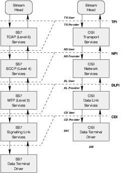
Each OpenSS7 protocol module provides standardized X/Open ISO/OSI interfaces as well as more SS7 specialized interfaces. Many of the OpenSS7 protocols modules provide TPI Revision 2.0 interfaces with support for the OpenSS7 XTI/TLI Library.
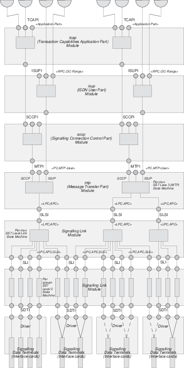
Figure 22 illustrates the organization of STREAMS modules, multiplexing drivers, pseudo-device drivers and real device drivers in the OpenSS7 SS7 stack. At each interface, the equivalent SIGTRAN User Adaptation Layer (UA) can be used. So, for example, between MTP Level 3 and its Users, the M3UA protocol can be employed. Each UA provides the same lower layer interface and upper layer interface. So, M3UA provides an MTP/MTP-User interface at its lower layer interface as well as at its upper layer interface.
8 Hardware Architecture
Figure 23 illustrates the hardware configuration for the OpenSS7 CNAM Query Platform.
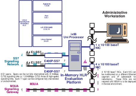
The OpenSS7 CNAM Query Platform consists of a medium end ix86 single processor PC in a hardened 19" rack mount chassis, loaded with RHAS4 Linux running a 2.6.20 kernel, streams-0.9.2.3, the OpenSS7 stack (strss7-0.9a.8) software and the CNAM Query Platform application.
SS7 or SIGTRAN signalling links are terminated either on E400P-SS7 cards (or other OpenSS7 compatible E1 cards) directly attached to the test platform, or via Signalling Gateway devices back-hauling M2UA, M3UA or SUA to the test platform over an internal LAN connection.
OAM&P of the prototype platform is performed over an internal LAN connection.
Hardware requirements are as follows:
- 1 x medium end (2.0 GHz) single processor, 19" rack mount, hardened chassis PC, 110 VAC commercial power.
- 2 x E400-SS7 Cards (or equivalent).
- 4 x 100baseT Ethernet NICs (3com 905B or equivalent).
For a redundant configuration (two hosts serving the same gateway), twice the hardware is required.
8.1 Interface Devices
The interface device hardware cards listed below are supported for the OpenSS7 Platform. All of the interface device hardware listed here has good price-performance, however, varying levels of performance (and therefore price) is available. These cards are available either directly from the card manufacturer or are also resold by OpenSS7 Corporation.
For the OpenSS7 CNAM Query Platform application, the V401P cards are recommended.
The following interface device hardware is available for the OpenSS7 Platform:
8.1.1 T400P/E400P-SS7
The T400P-SS7 and E400P-SS7 cards are 4-span T1 or E1 cards manufactured by Varion. These cards were previously manufactured by Digium. Figure 24 shows a picture of a T400P-SS7 card.
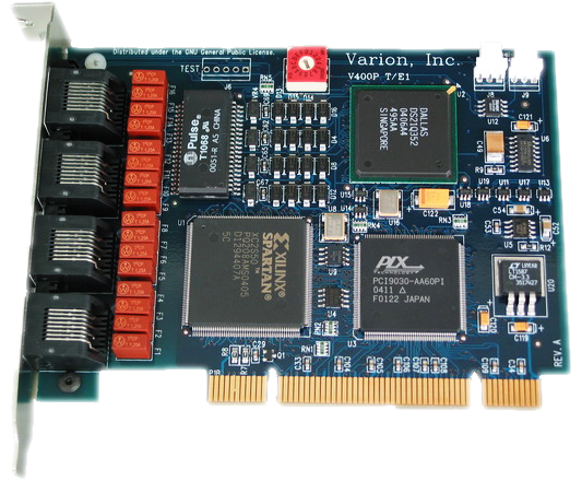
The T400P-SS7 and E400P-SS7 cards have the lowest level of signalling performance due to the lack of on-board HDLC functions. Transfers to the host processor over the PCI bus use PCI I/O ports and memory mapping.
Driver
These cards are supported by the X400-SS7 driver.
The function of the T/E400P-SS7 Channel driver is to provide for the termination of 2.048Mbps, 1.544Mbps, 64kbps and 56kbps digital paths. This driver provides direct access to the channelized or unchannelized T1 or E1 digital paths to OpenSS7 media and signalling protocol modules as well as providing T1 or E1 management, framing, coding, alarms, and synchronization.
Features
Following are the features of the T400P-SS7 and E400P-SS7 cards:
- 4 T1 or E1 spans per card.
- Dallas framer.
- PLX PCI 9030 PCI bus chip.
- Xilinx Spartan XC2S50 processor.
- Raw transfer of octets from framers to PCI bus.
- Uses OpenSS7 Soft-HDLC engine for SS7, ISDN and ISO.
- 96 channels per card (T400P-SS7)
- 124 channels per card (E400P-SS7).
- Full span addressable.
Advantages
Following are the advantages of the T400P-SS7 and E400P-SS7 cards:
- Low cost.
- PC Compatibility.
- Released by Jim Dixon under the GNU Public License.
- Open Hardware design: schematics, artwork and Gerber plots available.
- Flash programmable Xilinx chip.
- Field upgradable.
- Supports a number of Open Source drivers.
- Asterisk driver support.
Disadvantages
Following are the disadvantages of the T400P-SS7 and E400P-SS7 cards:
- Lower performance.
- No on-board HLDC.
- Cannot TDM switch on card or between cards, media channels must be transferred through host to switch between cards.
- I/O Port and Memory Map instead of PCI DMA bus-mastering and burst transfers.
- Does not run on high speed buses.
- No integrated Ethernet for SIGTRAN and VoIP applications.
- Synchronization per-card instead of per-system.
Ultimately, the performance limiting factor of the T400P-SS7 and E400P-SS7 cards is the bandwidth of the PCI bus and the ability of the processor to perform Soft-HDLC and TDM switching in software. A 350MHz processor is capable of processing the bandwidth of an entire E400P-SS7 card (124 signalling links) with a combined link throughput of 8.192 Mbps.
For the High Performance GSM/UMTS GPRS HLR, this performance is more than adequate. A medium grade 2GHz PC should be capable of handling 2 cards (248 SS7 links) with adequate excess capacity available for background operations.
These cards are very cost-effective and can provide 64kbps SS7 links at average incremental interface cost of approximately $8.00 USD per signalling link.
8.1.2 TE405/410-SS7
The TE405/410-SS7 cards are 4-span E1/T1 cards manufactured by Digium. These cards are a higher performance replacement for the T400P-SS7 and E400P-SS7 cards. Figure 25 shows a picture of a T405P-SS7 card.
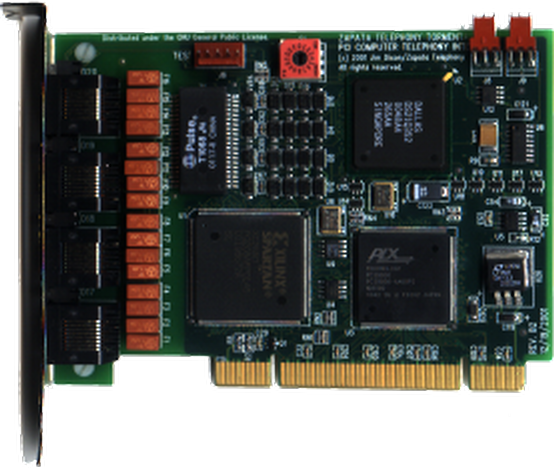
The TE405-SS7 and TE410-SS7 cards have a low level of signalling performance due to the lack of on-board HDLC functions. However, transfers to the host process over the PCI bus use bus-mastering PCI burst DMA transfers, unlike their T400P and E400P predecessors.
Driver
These cards are supported by the TE400-SS7 driver.
The function of the TE405/410-SS7 Channel driver is to provide for the termination of 2.048Mbps, 1.544Mbps, 64kbps and 56kbps digital paths. This driver provides direct access to the channelized or unchannelized T1 or E1 digital paths to OpenSS7 media and signalling protocol modules as well as providing T1 or E1 management, framing, coding, alarms, and synchronization.
Features
Following are the features of the TE405-SS7 and TE410-SS7 cards:
- 4 T1 or E1 spans per card.
- PMC Sierra framer
- PLX PCI 9030 PCI bus chip.
- Xilinx Spartan XC2S50 processor.
- Raw transfer of octets from framers to PCI bus.
- Uses OpenSS7 Soft-HDLC engine for SS7, ISDN and ISO.
- 96 channels per card (T1).
- 124 channels per card (E1).
- Full span addressable.
Advantages
Following are the advantages of the TE405-SS7 and TE410-SS7 cards:
- Lower cost.
- PCI DMA bus-mastering and burst transfers.
- Flash programmable Xilinx chip.
- Field upgradable.
- Supports a number of Open Source drivers.
- Asterisk driver support.
Disadvantages
Following are the disadvantages of the TE405-SS7 and TE410-SS7 cards:
- Lower performance, although better than predecessor.
- No on-board HLDC.
- Cannot TDM switch on card or between cards, media channels must be transferred through host to switch between cards.
- No integrated Ethernet for SIGTRAN and VoIP applications.
- Synchronization per-card instead of per-system.
As with their predecessors, the performance limiting factor of the TE405-SS7 and TE410-SS7 cards is the bandwidth of the PCI bus and the ability of the processor to perform Soft-HDLC and TDM switching in software. A 350MHz processor is capable of processing the bandwidth of an entire TE405-SS7 card (124 signalling link) with a combined linke throughput of 8.192 Mbps.
For the High Performance GSM/UMTS HLR, this performance is more than adequate. A medium grade 2GHz PC should be capable of handling 2 cards (248 SS7 links) with adequate excess capacity available for background operations.
These cards are cost-effective and can provide 64kbps SS7 links at average incremental interface cost of approximately $12.00 USD per signalling link.
8.1.3 A101/102/104c
The A101/102/104c cards are 1-, 2- and 4-span E1, T1 or J1 cards manufactured by Sangoma. Figure 26 shows a picture of an A101c card.
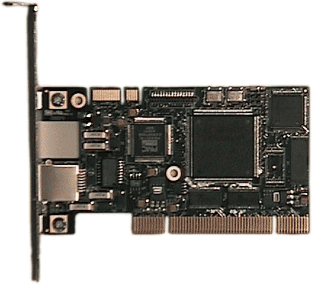
The A10Xc cards have an increased level of signalling performance due to availability of on-board HDLC processing. Transfers to the host are performed using bus-mastering PCI DMA burst transfers for lower host processor overhead. These cards do not support direct on-board TDM switching; neither do they have integrated Ethernet.
Driver
These cards are supported by the A100-SS7 driver.
The function of the A100-SS7 Channel driver is to provide for the termination of 2.048Mbps, 1.544Mbps, 64kbps and 56kbps digital paths. This driver provides direct access to the channelized or unchannelized T1 or E1 digital paths to OpenSS7 media and signalling protocol modules as well as providing T1 or E1 management, framing, coding, alarms, and synchronization.
Features
Following are the features of the A101c, A102c and A104c cards:
- 1, 2 or 4 E1 spans per card.
- PMC Comet framer.
- Xilinx Spartan XC2S50 processor.
- Raw transfer of octets from framers to PCI bus.
- Can use OpenSS7 Soft-HDLC engines for SS7, ISDN and ISO.
- Also provides for onboard HLDC (SS7 DAEDR/DAEDT AERM/SUERM).
- 24, 48 and 96 channels per card (T1 A101, A102 and A104).
- 31, 62 and 124 channels per card (E1 A101, A102 and A104).
- Full span addressable.
Advantages
Following are the advantages of the A101, A102 and A104 cards:
- Low cost.
- PC Comaptibility.
- Homolgomation and world-wide support.
- Flash programmable Xilinx chip.
- Field upgradable.
- Supports a wide range of Open Source drivers.
- Linux kernel WAN support.
- Asterisk driver support.
Disadvantages
Following are the disadvantages of the A101, A102 and A104 cards:
- Cannot TDM switch on card or between cards, media channels must be transferred through host to switch between cards.
- No integrated Ethernet for SIGTRAN and VoIP applications.
- Synchronization per-card instead of per-system.
The performance limiting factor of the A101c, A102c and A104c cards is the bandwidth of the PCI bus and the ability of the processor to perform TDM switching is software.
For the High Performance GMS/UMTS GPRS HLR, this performance is more than adequate, particularly as TDM switching is not a requirement for this pure signalling application. Although these cards lack integrated Ethernet support, for the non-redundant HLR application, and where interworking between SIGTRAN and SS7 is not required, this is not a limitation.
These cards have excellent price-performance and can provide 64kbps SS7 links at average incremental interface cost of approximately $12.00 USD per signalling link.
8.1.4 Other Interface Cards
Additional interface cards could be implemented in other phases of the project. For additional information, see Optional Hardware Support.
9 Logistics
Following are estimates of hardware, software, consulting, schedule and costs:
9.1 Hardware
Prototype hardware sufficient for trial of all projects consists of the following:
- 2 x high-end (2.0 GHz) PCs
- 6 x NICs (3 for each PC)
- 4 x A104 Cards (2 for each PC)
9.1.1 Sizing Considerations
Sizing provided here is adequate to meet the scale requirements under System Architecture. For detail on sizing, see Platform Sizing.
9.2 Software
Prototype software sufficient for trial of all projects consists of the following:
- WhiteBox EL3 Linux distribution (or equivalent)
- Linux 2.4.21 kernel (GPL, download)
- Linux Fast-STREAMS (openss7-1.1.7.20141001 or equivalent, GPL download)
- OpenSS7 CVS access
- OpenSS7 components listed under project
9.3 Consulting
Consulting consists of the following:
- Completion of OpenSS7 components marked as "incomplete" under project description suitable for use for prototype.
- Development and documentation of "application" components under project descriptions.
- Loading and configuring software for evaluation platforms.
- Participating in evaluation testing.
- Answering questions and providing guidance to client staff on the use and testing of the evaluation platform.
9.4 Schedule
Below is an estimated schedule. The estimate considers that OpenSS7 staff would be performing all development work and that Gamma client or Sponsor would participate in external gate reviews and acceptance testing in a timely manner.
Table S-0 lists the initial (Gate 0) schedule estimates.
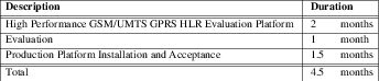
Table S-1 through Table S-8 list the current (Gate 1) schedule estimates. These are planning estimates only and no commitment is provided to deliver to any schedule until Gate 2 is complete.
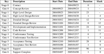
9.4.1 Gate 0 — Concept
Gate 0 is passed when the initial concept has been elucidated and work is begun on a High-Level Design. This is an internal OpenSS7 gate. Table S-2 below lists the estimated schedule leading into Gate 0.
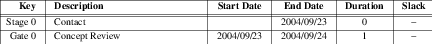
Gate 0 was completed for the project on September 24, 2004 with the creation of the Initial design document and internal OpenSS7 staff decision to move forward with a High-Level Design.
9.4.2 Gate 1 — High-Level Design
Gate 1 is passed when the high-level design has been reviewed to the satisfaction of the consumers of the project. This is an external review gate. OpenSS7 internally passes this gate once the High-Level Design has been published and work is begun on a detailed design. 10 Table S-3 below lists the estimated schedule leading into Gate 1.
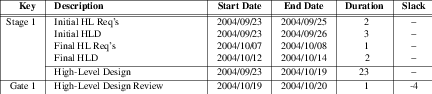
This document completes the Gate 1 requirements October 20, 2004. We are currently awaiting external review of this document and proceeding on Detailed Design documentation.
9.4.3 Gate 2 — Detailed Design
Gate 2 is passed when the detailed design has been reviewed to the satisfaction of the consumers of the project and the developers on the project. This is an external as well as an internal review gate. OpenSS7 passes this gate once the Detailed Design has been published and work base begin on development and implementation of the design. 11 Passing this gate moves from the design stage to the development stage of the project. Table S-4 below lists the estimated schedule leading into Gate 2.
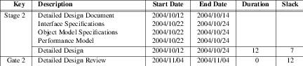
9.4.4 Gate 3 — Development and Implementation
Gate 3 is passed when the software and systems development and implementation to the detailed design is complete and testing has begun. This is an internal review gate. OpenSS7 internally passes this gate when software is code complete and hardware has been installed for testing. Table S-5 below lists the estimated schedule leading into Gate 3.
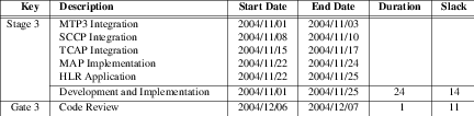
9.4.5 Gate 4 — System Test
Gate 4 is passed once the product implementation meets all internal ad hoc and formal conformance test suites and internal testing is complete. This is an internal review gate. OpenSS7 passes this gate internally once conformance testing is complete. Passing this gate moves from the development stage to the support stage of the project. Table S-6 below lists the estimated schedule leading into Gate 4.
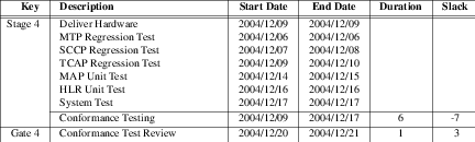
9.4.6 Gate 5 — Acceptance Testing
Gate 5 is passed once the product implementation has passed external Gamma client acceptance testing. This is an external review gate. OpenSS7 passes this gate internally once participation in external acceptance testing is complete. Table S-7 below lists the estimated schedule leading into Gate 5.
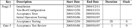
9.4.7 Gate 6 — Support Complete
Gate 6 is passed once all support obligations for the product implementation have been discharged. This is an internal review gate. OpenSS7 passes this gate once support agreements have terminated. Table S-8 below lists the estimated schedule leading into Gate 6.
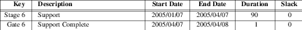
9.5 Cost
Table T-2 below provides a cost estimate. The estimate is in US Dollars and assumes that all Evaluation platform hardware would be provided by OpenSS7 and that all Signalling Gateway, STP and Cross-Connect hardware, Routers and LAN, and other sundry lab equipment be provided by the client. Development time is estimated at 100% effort per calendar week at our normal loaded rate. Shipping costs, training, training material and travel costs are not listed and would be billed separately.
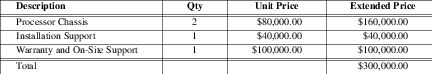
Appendix A Optional Application Support
A.1 Other Solution Architecture
A.1.1 Ferry Clip Testing
The other possible test arrangement is the Ferry Clip arrangement. In this case, the OpenSS7 Test Platform behaves like the 3GPP GSM/UMTS network surrounding the SGSN Implementation Under Test. This is illustrated in Figure A-1 below.
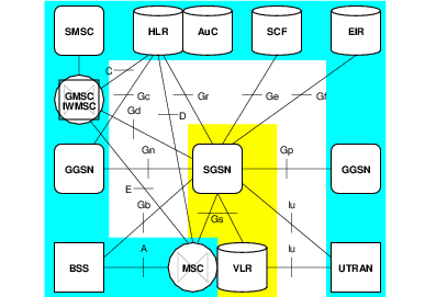
Appendix B Optional Network Support
B.1 SGSN Reference Interfaces
Figure A-2 illustrates the SGSN Reference Interfaces from 3GPP TS 24.060 Release 5.9.0 that are supported by the High Performance GSM/UMTS GPRS HLR.
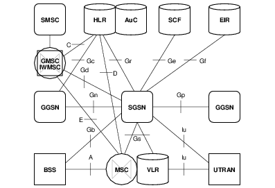
- Iu Interface
This connects the 3G SGSN to a UTRAN.
- Gb Interface
This connects the 2G SGSN to a BSS.
- Gd Interface
This connects the 3G SGSN to a SMS-GMSC or SMS-IWMSC.
- Ge Interface
This connects the 3G SGSN to a Camel GSM SCF.
- Gn Interface
This connects the 3G SGSN to a (local) GGSN.
- Gp Interface
This connects the 3G SGSN to a (foreign) GGSN.
- Gs Interface
This connects the 3G SGSN to an MSC/VLR.
B.1.1 Iu Interface
The Iu interface connects the 3G SGSN to the UTRAN.
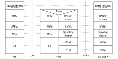
UMTS Mobility Management and Session Management (GMM/SM): GMM supports mobility management functionality such as attach, detach, security, and routing area update, as described in "Mobility Management Functionality". SM supports PDP context activation and PDP context deactivation, as described in "PDP Context Activation, Modification, Deactivation, and Preservation Functions" of TS 23.060.
SMS supports the mobile-originated and mobile-terminated short message service described in 3GPP TS 23.040.
Radio Access Network Application Protocol (RANAP): This protocol encapsulates and carries higher-layer signalling, handles signalling between the 3G-SGSN and UTRAN, and manages the GTP connections on the Iu interface. RANAP is specified in 3GPP TS 25.413. The layers below RANAP are defined in 3GPP TS 23.121.
Radio Link Control (RLC): The RLC protocol offers logical link control over the radio interface for the transmission of higher layer signalling messages and SMS. RLC is defined in 3GPP TS 25.322. RLC for GSM is described in GSM 04.60.
For transport of RANAP messages over Iu an SCCP protocol shall be used for both packet and circuit switche domains. The SCCP protocol shall fully comply with ITU-T White Book. RANAP protocol shall be designed to use this service according to the ITU-T standard. Iu shall be design so that RANAP is not impacted by alternatives for SCCP message transport on layers below SCCP.
In the circuit switched domain, SCCP message shall be transported on a broadband SS7 stack comprising MTP3b on top of SAAL-NNI. In this domain no other alternatives are standardized in release 99.
In the packet switched domain the UMTS standard shall allow operators to choose one our of two standardized protocol suites for transport of SCCP messages.
- Broadband SS7 stack comprising MTP3b on top of SAAL-NNI.
- IETF/Sigtran CTP protocol suite for MTP3 users with adaptation to SCCP. The protocol suite shall fully comply with IETF standards developed by the Sigtran working group. No UMTS specific adaptation shall be standardized below the SCCP protocol.
See aslo TS 29.202 which provides the following signalling bearers:
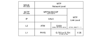
B.1.2 Gb Interface
The Gb interface connects the 2G SGSN to the BSS.
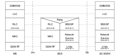
GPRS Mobility Management and Session Management (GMM/SM): This protocol supports mobility management functionality such as GPRS attach, GPRS detach, security, routing area update, location update, PDP context activation, and PDP context deactivation, as described in "Mobility Management Functionality" and "PDP Context Activation, Modification, Deactivation, and Preservation Functions" of TS 23.060.
Radio Link Control (RLC): The RLC protocol offers logical link control over the radio interface for the transmission of higher layer signalling messages and SMS. RLC is defined in 3GPP TS 25.322. RLC for GSM is described in GSM 04.60.
Logical Link Control (LLC):- LLC is defined in GSM 04.64.
BSS GPRS Protocol (BSSGP):- BSSGP is defined in GSM 08.18.
Network Service:- The Network Service is defined in GSM 08.16.
The Network Service consists of a network services protocol over a Frame Relay (FRF 1.1) Sub-Network Service Protocol.
L1 of the Gb interface is defined in GSM 08.14 and consists of one or more of the following FRF 1.1 supporting interfaces:
- ANSI T1.403
- V.35, physical circuit and DTE/DCE interface
- G.703
- G.704
- X.21
- ANSI-530-A-1992
- HSSI
The Gb interface may be multiplexed with the A interface on the same E1 (2048 kbit/s), or T1 (1544 Kbit/s) digital path. In the case of E1 interface, CCITT Recommendation G.704 shall be applied and 3GPP TS 08.04 as appropriate, and in case of T1 interface ANSI Recommendation T1.403 shall be applied and 3GPP TS 08.04 as appropriate. In the case where multiple 64 kbit/s channels are used on an E1 (2048 kbit/s) digital patch on the Gb interface, it is recommended to aggregate them into one nx64 kbit/s channel, see CCITT Recommendation G.704, clause 5 and included sub-clauses. In case where multiple 64 kbit/s channels are used on a T1 (1544 kbit/s) digital path on the Gb interface, it is recommended to aggregate them into nx64kbit/s (where 2<=n<=24) channel, see Bellcore TR-NWT-1203. This approach optimizes the use of the available bandwidth by taking advantage of the statistical multiplexing at the upper layer. However, this approach requires that no slipping occurs between individual 64 kbit/s channels e.g. when passing through intermediate equipment between BSS and SGSN.
The physical channels on the Gb interface shall be permanently reserved by means of administrative procedures.
B.1.3 Gd Interface
The Gd interface connects the 3G SGSN to the SMS-GMSC or SMS-IWMSC.
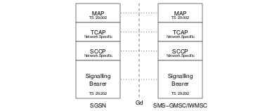
Mobile Application Part (MAP):- This protocol supports signalling between SGSN and SMS-GMSC or SMS-IWMSC, as described in clause "Point-to-point Short Message Service" of 3GPP TS 23.060.
B.1.4 Ge Interface
The Ge interface connects the 3G SGSN to the Camel GSM SCF.
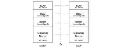
B.1.5 Gf Interface
The Gf interface connects the 2G SGSN to the EIR.
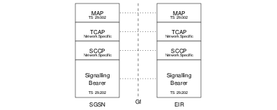
Mobile Application Part (MAP):- This protocol supports signalling between the SGSN and the EIR, as described in "Identify Check" of 3GPP TS 23.060.
B.1.6 Gn Interface
The Gn interface connects the 3G SGSN to the local GGSN.
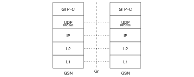
GPRS Tunnelling Protocol for the control plane (GTP-C):- This protocol tunnels signalling messages between SGSNs and GGSNs (Gn), and between SGSNs in the backbone network (Gp).
User Datagram Protocol (UDP):- This protocol transfers signalling messages between GSNs. UDP is defined in RFC 768.
B.1.7 Gp Interface
The Gp interface connects the 3G SGSN to the foreign GGSN.

GPRS Tunnelling Protocol for the control plane (GTP-C):- This protocol tunnels signalling messages between SGSNs and GGSNs (Gn), and between SGSNs in the backbone network (Gp).
User Datagram Protocol (UDP):- This protocol transfers signalling messages between GSNs. UDP is defined in RFC 768.
B.1.8 Gs Interface
The Gs interface connects the 3G SGSN to the MSC/VLR.
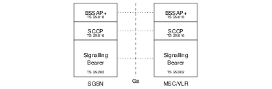
Base Station System Application Part + (BSSAP+):- A subset of BSSAP procedures supports signalling between the SGSN and MSC/VLR, as described in "Mobility Management Functionality" in 3GPP TS 23.060 and in 3GPP TS 29.018. The requirements for the lower layers are specified in 3GPP TS 29.016.
Additional information about supported signalling bearers is provided in 3GPP TS 29.202 as follows:
Appendix C Optional Protocol Support
C.1 Other Protocol Components
C.1.1 SCCP User Adaptation Layer (SUA) Driver
The SUA driver provides the HLR with the ability to act as an SUA AS (Application Server) in conjunction with an SUA SG (Signalling Gateway). In this project, the SG function is performed by existing lab equipment. The SUA driver accepts the transport of the SCCP to SCCP-User interface from the SG to the HLR. The SUA driver links SCTP driver streams underneath it to provide the transport services for exporting the SCCP-User interface. The SUA driver provides the same interfaces to its users as the OpenSS7 SCCP.
The SUA driver is a STREAMS driver that runs in the Linux kernel for maximum performance.
C.1.2 MTP Level 3 Broadband (MTP3b) Module
C.1.3 Service Specific Connection Oriented Protocol (SSCOP) Driver
C.1.4 MTP Level 2 User Adaptation Layer (M2UA) Driver
The M2UA driver provides the HLR with the ability to act as an M2UA AS (Application Server) in conjunction with an M2UA SG (Signalling Gateway). In this project, the SG function is performed by existing lab equipment. The M2UA driver accepts the transport of the SL to SL-User interface from the SG to the HLR. The M2UA driver links SCTP driver streams underneath it to provide the transport services for exporting the SL-User interface. The M2UA driver provides the same interface to its users as the OpenSS7 SL module.
Appendix D Optional Software Support
D.1 Operating System Options
OpenSS7 components and applications support the following additional Linux Distributions:
- RedHat Linux 7.2 (rh7.2)
- RedHat Linux 9 (rh9)
- RedHat Linux EL3 (el3)
- Fedora Core 1 (fc1)
- Debian (Woody)
- SuSE 8.0
D.2 STREAMS Options
D.2.1 Linux Fast-STREAMS (LfS)
Linux Fast-STREAMS (LfS) is a dual licensed original work of OpenSS7 Corporation. It was designed an implemented as a directly replacement for inferior implementations for use with OpenSS7 stack releases. This complete reimplementation of an SVR 4.2 ES/MP compatible STREAMS facility exhibits simplified debugging and management, greatly increased performance, smaller memory footprint, wider compatibility. Production releases of Linux Fast-STREAMS are currently available.
Appendix E Optional Hardware Support
E.1 Other Interface Devices
This section provides information on additional interface cards available for use with the OpenSS7 SS7, SIGTRAN, ISDN and VoIP stacks:
E.1.1 ACB56
The ACB56 cards are single V.35 56/64kbps synchronous cards manufactured by SeaLevel Systems and distributed by ICS. Figure A-13 shows a picture of an ACB56 card.
Driver
The driver for the ACB56 card provides, CH, SDL or SDT access to the card. The CH or SDL driver places the Zilog part into transparent mode and passes octets directly off the line to the channel or signalling data link driver. The SDT driver places the Zilog part into HDLC mode and performs SS7 HDLC using the Zilog SCC. The SDT driver performs better, of course, than the CH or SDL drivers, however, the Zilog SCC HDLC is incapable of performing some SS7 functions that are provided by the OpenSS7 SDT (SS7-HDLC) module for the CH or SDL drivers.
Features
Following are some features of the ACB56 card:
- 1 x V.35 56kbps or 64 kbps synchronous port on DB-25 connector.
- DB-25 to N-type cable available.
- 56 kbps or 64kbps DTE mode.
- 56 kbps DCE mode.
- Based on Zilog 80585 Serial Communications Controller (SCC).
- ISA Bus.
- Supports dual-channel ISA DMA.
- Also supports RS-232C although not useful for SS7.
Advantages
Following are the advantages of the ACB56 card:
- Provides V.35 interface where necessary.
The ACB56 card has few advantages. It only provides low-cost V.35 interface where absolutely necessary. Any other V.35 capable card might be a better choice.
Disadvantages
Following are the disadvantages of the ACB56 card:
- ISA bus.
- Low density.
- Limited number of cards per host due to ISA IRQ and DMA limitations.
- Needs external CSU/DSU.
- Does not support TDM voice channels.
Due to its disadvantages, another V.35 card (PCI based, higher density, integrated CSU/DSU) should be considered where V.35 interface is completely necessary.
The High Performance GSM/UMTS GPRS HLR does not have a requirement for V.35 interface and this card is not used on the deployment platform. If V.35 interface becomes a requirement at a later date, a different card will be selected. The selected card will have a higher density, PCI with PCI DMA and bus-mastering, integrated CSU/DSU, and other features absent from the ACB56 card.
E.1.2 PCA 200E
The PCA 200E card is a 155MHz ATM card manufactured by Marconi (formerly FORE). Figure A-16 shows a picture of an PCA 200E card.
The PCA 200E cards have a good level of signalling performance because they have an on-board 25MHz i960 Intel RISC processor performing cell processing using buffer rings in the same manner as an Ethernet controller.
Driver
Features
Following are the features of the PCA 200E cards:
- 155 MHz ATM, ST/SC SM/MM and RJ-45 UTP 5
- AAL1, AAL2, AAL3 and AAL5 modes.
- Integrated 25 MHz i960 RISC cell processor.
- Enhance SAR Processor (ESP) ASIC
- Special-purpose hardware for AAL5 and AAL3/4, HEC, and CRC calculations.
- Dual-ported RAM and Buffer Ring technique similar to Ethernet Controller.
- Serial communications emulation.
- Supports ABR
- ATM cell processing per ANSI T1S1.5/92-002R3, ITU I.361, ATM Form UNI v3.0, 3.1, 4.0
Advantages
Following are the advantages of the PCA 200E cards:
- Inexpensive (about $200 a card).
- Supports MTP3b.
- Can support 3GPP UMTS Iu User and Control Plane over PVCs.
Disadvantages
Following are the disadvantages of the PCA 200E cards:
- Does not support traditional SS7 links.
- Requires external ATM switch or point-to-point ATM connection.
E.1.3 BRI
A BRI card.
Driver
Features
Following are the features of the BRI cards:
Advantages
Following are the advantages of the BRI cards:
Disadvantages
Following are the disadvantages of the BRI cards:
Appendix F Programmatic Interfaces
To support a framework for providing transaction products in the UNIX system, an effort is underway to define service interfaces to map to strategic levels of the Signalling System Number 7 (SS7) model. These service interfaces hide implementation details of a particular service from the consumer of the service. This enables system programmers to develop software independent of the particular protocol that provides a specific service. The interfaces being specified for UNIX System V are defined within the STREAMS environment. This document specifies a kernel-level interface that supports the services of the Transaction Capabilities Application Part for Operation Class 1, 2, 3 and 4 services.
This specification applies to System V Release 4.2 ES/MP STREAMS.
F.1 Transaction Component Interface
The transaction component interface defines a message interface to a transaction provider implemented under STREAMS. 12 A user communicates to a transport provider via a full duplex path known as a stream (see Figure F-1). This stream provides a mechanism in which messages may be passed to the transaction provider from the transaction user and visa versa.
|
Figure F-1 - Example of a stream from a user to a transaction provider
|
The STREAMS messages that are used to communicate transaction service primitives between the transaction user and the transaction provider may have one of the following formats:
- A
M_PROTOmessage block followed by zero or moreM_DATAmessage blocks. TheM_PROTOmessage block contains the type of transaction service primitive and all the relevant arguments associated with the primitive. TheM_DATAblocks contain transaction user data associated with the transaction service primitive.
F.1.1 Common Transaction Primitives
The following transaction primitives are common to all operation classes:
F.1.1.1 User-Originated Primitives
The following describes the format of the transaction primitives which are generated by the transaction user.
TC_INFO_REQ - get transaction protocol parameter sizes
This primitive requests the transaction provider to return sizes of all relevant protocol
parameters, plus the current state of the provider.13. The format of the message is one M_PCPROTO message block. The
format of the M_PCPROTO message block is as follows:
struct TC_info_req {
        long PRIM_type;             /* always TC_INFO_REQ */
};
F.1.2 TCI Model
F.1.3 TC Interface Local Management Primitives
The following local management primitives provide local management functions within the STREAMS environment that are not standardized (implementation dependent). Some of the functions are informatively described in ITU-T Recommendation Q.771.
Local Management primitives:
TC_INFO_REQ, TC_INFO_ACKInformation request and acknowledgement. Returns the maximum dialogue SDU size for begin, continue and end, the interface SDU size, the maximum address size, maximum options size, service type, current state, provider flags and version.
TC_OPTMGMT_REQ, TC_OPTMGMT_ACKOptions management request and acknowledgement. Negotiates options according to management flags.
TC_BIND_REQ, TC_BIND_ACKBind to transport address request and acknowledgement. Contains the transport address for the bind and the maximum negotiated number of outstanding transactions.
TC_SUBS_BIND_REQ, TC_SUBS_BIND_ACKSubsequent bind to transport address request and acknowledgement.
TC_SUBS_UNBIND_REQSubsequent unbind from transport address request.
TC_UNBIND_REQUnbind from transport address request.
TC_OK_ACKSuccess acknowledgement. Returns the primitive that was successful.
TC_ERROR_ACKError acknowledgement. Returns the primitive that was unsuccessful, the error code (transport or UNIX), dialogue identifier and component identifier.
F.1.4 TC Interface Dialogue Handling Primitives
The following dialogue handling primitives correspond to the primitives described in ITU-T Recommendation Q.771.
Dialogue Handling primitives:
TC_UNI_REQ, TC_UNI_INDUnidirectional dialogue request and indication. Includes the source transport address, the destination transport address, associated negotiated options, dialogue identifier and component flags.
TC_BEGIN_REQ, TC_BEGIN_IND, TC_BEGIN_RES, TC_BEGIN_CONBegin dialogue request, indication, response and confirmation. Includes the source transport address, the destination transport address, associated negotiated options, dialogue identifier and component flags.
TC_CONT_REQ, TC_CONT_INDContinue dialogue request and indication. Includes the associated negotiated options, dialogue identifier and component flags.
TC_END_REQ, TC_END_INDEnd dialogue request and indication. Includes the associated options, dialogue identifier, component flags and termination scenario.
TC_ABORT_REQ, TC_ABORT_INDAbort dialogue request and indication. Includes the associated negotiated options, dialogue identifier, abort reason and originator.
TC_NOTICE_INDNotice indication. Includes the report cause.
F.1.5 TC Interface Component Handling Primitives
The following component handling primitives correspond to the primitives described in ITU-T Recommendation Q.771.
Component Handling primitives:
TC_INVOKE_REQ, TC_INVOKE_INDInvoke operation request and indication. Includes the dialogue identifier, application protocol class, invoke identifier, linked invoke identifier, invoke operation, segmentation flag, and requested timeout.
TC_RESULT_REQ, TC_RESULT_INDReturn result to operation request and indication. Includes the dialogue identifier, invoke identifier, invoke operation, and segmentation flag.
TC_ERROR_REQ, TC_ERROR_INDError of operation request and indication. Includes the dialogue identifier, invoke identifier, error code and segmentation flag.
TC_REJECT_REQ, TC_REJECT_INDReject operation request and indication. Includes the dialogue identifier, invoke identifier, originator, and problem code.
TC_CANCEL_REQ, TC_CANCEL_INDCancel component request and indication. Includes the dialogue identifier and invoke identifier.
F.2 Mobile Application Part Interface
F.2.1 MAP Interface Common Primitives
For a mapping of Common MAP primitives onto TC primitives, see 3GPP TS 29.002 Table 7.5/1 and Table 7.5/2.
MAP_OPEN_REQ, MAP_OPEN_IND, MAP_OPEN_RES, MAP_OPEN_CONOpens a MAP dialogue. Contains application context name, destination address and reference; originating address and reference; specific information, responding address, result, refusal-reason, provider error.
MAP_DELIMITERDelimits a sequence of components in a MAP dialogue.
MAP_CLOSE_REQ, MAP_CLOSE_INDCloses a MAP dialogue. Contains release method and specific information.
MAP_ABORT_REQ, MAP_ABORT_INDAborts a MAP dialogue. Include user reason, diagnostic information and specific information; or, provider reason and source.
MAP_NOTICEProtocol problem notice. Includes the problem diagnostic.
MAP_SXPORT_REQ, MAP_SXPORT_IND, MAP_SXPORT_RES, MAP_SXPORT_CONMAP secure transport. Includes operation class, security header, protected payload, user error or provider error.
F.2.2 MAP Interface User-Specific Primitives
For a mapping of User-Specific primitives onto TC primitives, see 3GPP TS 29.002 Table 7.5/3 and Table 7.5/4.
Appendix G Platform Sizing
Table T-1 below provides a traffic model for sizing the HLR application.
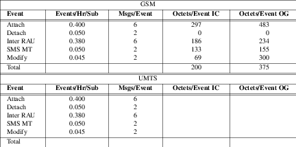
G.1 HLR Sizing
Phase 1 imposes HLR sizing requirements as follows:
- — Number of Subscriber Records
To support the HLR application, the number of subscriber records supported is 15 million.
- — Number of Subscriber Templates
To support the HLR application, subscriber templates will be used where possible. There is no hard limit on the number of subscriber templates (up to the number of subscriber records). The expected number of subscriber templates provided is 1024.
- — Amount of Physical Memory
To support in-core access to the entire subscriber database, 2 Gbytes of physical memory is provided.
- — Event Rate
From Table T-1 with 15 million subscribers, the event rate provided is 3855 events per second. The in-core database will provide a transaction rate of 4000 transactions per second.
Phase 2 does not add any additional HLR sizing requirements.
G.2 MAP/TCAP Sizing
Phase 1 imposes MAP/TCAP sizing requirements as follows:
- — Transaction Rate
From Table T-1 with 15 million subscribers, the MAP/TCAP transaction rate provided is 10,000 MAP/TCAP transactions per second.
- — Number of Simultaneous open Transactions
Although the OpenSS7 TCAP component does not have a hard limit on the number of open TCP transactions, the component can be optimized for an expected maximum number of open transactions. To meet the expected transaction rate and MAP loading, the TCAP component is optimized for a maximum of 4096 open transactions. If open transactions exceed 4096, performance is degraded. Open transactions fewer than 4096 wil have no impact on the platform.
G.3 SCCP Sizing
Phase 1 imposes SCCP sizing requirements as follows:
- — Number of Protocol Variants
The OpenSS7 SCCP component provides simultaneous support for ITU-T, ETSI and ANSI protocol variants in a single protocol module. To support the Phase 1 HLR application, three protocol variants will be provided:
- ITU-T SCCP Q.713 1988/93
- ETSI SCCP Q.713 1988/93
- ANSI T1.112/1996
- — SCCP Routing
Although the OpenSS7 SCCP component supports a wide range of routing, including local GTT, to meet the HLR application requirements, routing will be performed on PC only.
- — Number of Local Subsystems
Although there is no hard limit on the number of local subsystems that can be supported by the OpenSS7 SCCP protocol component, to support the HLR application, two local subsystems are provided:
- One HLR subsystem is provided associated with an ITU-T/ETSI point code in the ITU-T/ETSI domain.
- Another HLR subsystem is provided associated with an ANSI point code in the ANSI domain.
- — Number of Remote Signalling Points
Although there is no hard limit on the number of remote signalling points that can be supported by the OpenSS7 SCCP protocol component, to support the HLR application, six (6) remote signalling points are provided:
- One (1) remote signalling point codes for one SGSN in the ITU-T/ETSI domain.
- One (1) remote signalling point codes for one SGSN in the ANSI domain.
- One (1) remote signalling point codes for another SGSN in the ITU-T/ETSI domain.
- One (1) remote signalling point codes for another SGSN in the ANSI domain.
- One (1) remote signalling point codes for a SMS-IWMSC/GMSC platform in the ITU-T/ETSI domain.
- One (1) remote signalling point codes for a SMS-IWMSC/GMSC platform in the ANSI domain.
- — Number of Remote Subsystems
Although there is no hard limit on the number of remote subsystems that can be supported by the OpenSS7 SCCP protocol component, to support the HLR application, six (6) remote subsystems are provided:
- One (1) remote SGSN subsystems for one SGSN in the ITU-T/ETSI domain.
- One (1) remote SGSN subsystems for one SGSN in the ANSI domain.
- One (1) remote SGSN subsystems for another SGSN in the ITU-T/ETSI domain.
- One (1) remote SGSN subsystems for another SGSN in the ANSI domain.
- One (1) remote MSC subsystems for a SMS-IWMSC/GMSC platform in the ITU-T/ETSI domain.
- One (1) remote MSC subsystems for a SMS-IWMSC/GMSC platform in the ANSI domain.
Phase 2 does not add any additional MAP/TCAP sizing requirements.
G.4 MTP Sizing
Phase 1 imposes MTP Level 3 sizing requirements as follows:
- — Number of Protocol Variants
The OpenSS7 MTP component provides simutaneous support for ITU-T, ETSI and ANSI protocol variants in a single protocol module. To support the Phase 1 HLR application, three protocol variants will be provided:
- ITU-T MTP Q.703/Q.704 1988/93
- ETSI MTP Q.703/Q.704 1988/93
- ANSI MTP T1.111/1996
- — Number of Signalling Points
Although there is no hard limit on the number of local signalling points that can be supported by the OpenSS7 MTP protocol component, to support the HLR application, two (2) local signalling points are provided:
- One local signalling point in the ITU-T/ETSI domain.
- One local signalling point in the ANSI domain.
- — Number of Point Codes
Although there is no hard limit on the number of signalling point codes per local signalling point that can be supported by the OpenSS7 MTP protocol component, to support the HLR application, two (2) signalling point codes are provided:
- One signalling point code in the ITU-T/ETSI domain.
- One signalling point code in the ANSI domain.
- — Number of Route Sets
Although there is no hard limit on the number of remote signalling points (routesets) that can be supported by the OpenSS7 MTP protocol component, to support the HLR application, six (10) routesets are provided:
- One (1) routeset for one SGSN in the ITU-T/ETSI domain.
- One (1) routeset for one SGSN in the ANSI domain.
- One (1) routeset for another SGSN in the ITU-T/ETSI domain.
- One (1) routeset for another SGSN in the ANSI domain.
- One (1) routeset for an SMS-IWMSC/GMSC in the ITU-T/ETSI domain.
- One (1) routeset for an SMS-IWMSC/GMSC in the ANSI domain.
- Two (2) routesets, one for each mated pair of STPs in the ITU-T/ETSI domain.
- Two (2) routesets, one for each mated pair of STPs in the ANSI domain.
- — Number of Signalling Link Sets
Although there is no hard limit on the number of signalling link sets that can be supported by the OpenSS78 MTP protocol component, to support the HLR application, two (2) combined linksets for a total of four (4) linksets are provided:
- One (1) combined A-linkset or two (2) A-linksets, one for each mated pair of STPs in the ITU-T/ETSI domain.
- One (1) combined A-linkset or two (2) A-linksets, one for each mated pair of STPs in the ANSI domain.
- — Number of Signalling Links
Table T-1 provides a traffic model for the required number of signalling links. Worst case traffic at 15 million subscribers is as follows: 375 octets per subscriber per hour, or 12.5 Mbps of signalling links. This will require 195 low speed signalling links, or 6.3 Q.703 Annex B high-speed signalling links.
To support the HLR application, signalling links will be provided as follows:
- – Eight high-speed (2.048 Mbps) signalling links (E1), alternately in the ITU-T/ETSI domain or in the ANSI domain.
- – Because the number of low-speed signalling links would far exceed the ANSI maximum of 32, low-speed signalling links cannot be used for 15 million subscriber tests.
- — Numebr of Interface Cards
To support the SS7 signalling links will require:
- – Two E400P-SS7 card; or,
- – Two TE410-SS7 card; or,
- – Two A104c card; or,
- – Two PCI 384 card.
Phase 2 imposes SCCP sizing requirements as follows:
- — SCCP Protocol Variants
The OpenSS7 SCCP component provides simultaneous support for ITU-T, ETSI and ANSI protocol variants in a single protocol module, and is unaffected by whether the underlying message transfer part is SS7 MTP Level 3 or M3UA.
- — SCCP Routing
Phase 2 does not impose any new SCCP routing requirements and routing will still be performed on PC only.
- — Number of Local Subsystems
To support M3UA, two additional subsystems are provided:
- One HLR subsystem for the ITU-T M3UA ASP.
- Another HLR subsystem for the ANSI M3UA ASP.
- — Number of Remote Signalling Points
Phase 2 does not impose any new requirements on the number of remote signalling points.
- — Number of Remote Subsystems
Phase 2 does not impose any new requirements on the number of remote signalling subsystems.
G.5 M3UA Sizing
Phase 2 adds requirements for M3UA sizing as follows:
- — Number of Protocol Variants
The OpenSS7 M3UA component provides simultaneous support for ITU-T, ETSI and ANSI protocol variants in a single protocol module. To support the Phase 1 HLR application, three protocol variants will be provided:
- ITU-T MTP Q.703/Q.704 1988/93
- ETSI MTP Q.703/Q.704 1988/93
- ANSI MTP T1.111/1996
These protocol variants will be provided in two (2) Network Appearances:
- One network appearance in the ITU-T/ETSI domain.
- One network appearance in the ANSI domain.
- — Number of Signalling Points
Phase 2 adds the requirement for two (2) additional signalling points:
- One local signalling point in the ITU-T/ETSI domain.
- One local signalling point in the ANSI domain.
- — Number of Point Codes
Phase 2 adds the requirement for two (2) additional signalling point codes:
- One signalling point code in the ITU-T/ETSI domain.
- One signalling point code in the ANSI domain.
- — Number of Application Server Processes
Provision for 1 Application Server Process. The HLR will represent a single Application Server Process within the M3UA domain.
- — Number of Application Servers
Provision for 2 M3UA Application Servers:
- One M3UA ASP is provisioned on the HLR within an ITU-T/ETSI network appearance requiring 1 ITU-T SS7 Signalling Point Code. This ASP utilizes a Routing Key that consists of the ITU-T Network Appearance, ITU-T DPC, and SI value for SCCP (3).
- Another M3UA ASP is provisioned on the HLR within an ANSI network appearance requiring 1 ANSI SS7 Signalling Point Code. This ASP utilizes a Routing Key that consists of the ANSI Network Appearance, ANSI DPC, and SI value for SCCP (3).
Each ASP is an Override AS that has only one active ASP within the AS.
G.6 SCTP Sizing
Phase 2 adds requirement for SCTP sizing as follows:
- — Number of Associations
Although there is no hard limit to the number of SCTP associations that can be supported by the OpenSS7 SCTP component, to meet the HLR requirements, two (2) associations will be provided:
- One association between the HLR and one SG acting as an STP mated pair.
- One association between the HLR and another SG acting as an STP mated pair.
These two associations will each support the two Application Servers listed above under M3UA sizing.
G.7 IP/Ethernet Sizing
Phase 2 adds requirement for IP/Ethernet sizing as follows:
- — IP Addresses
Two additional IP addresses and interfaces will be provided to accommodate SCTP multihomed associations.
- — Ethernet Interfaces
Two additional Ethernet 100baseT NICs will be provided to accommodate M3UA traffic. Because worst case traffic is estimated per Table T-1 at 15 millions subscribers at 25 Mbps, these additional NICs should accommodate full M3UA traffic.
- — Ethernet Switch
A 100baseT Layer 2 switch is provided to ensure that M3UA/SCTP traffic is not hubbed.
Index
| Jump to: | A B C D E F G H I L M N O P Q R S T V X |
|---|
| Jump to: | A B C D E F G H I L M N O P Q R S T V X |
|---|
Short Table of Contents
- Executive Overview
- Preface
- 1 Introduction
- 2 Application Architecture
- 3 Network Architecture
- 4 System Architecture
- 5 Platform Architecture
- 6 Protocol Architecture
- 7 Software Architecture
- 8 Hardware Architecture
- 9 Logistics
- Appendix A Optional Application Support
- Appendix B Optional Network Support
- Appendix C Optional Protocol Support
- Appendix D Optional Software Support
- Appendix E Optional Hardware Support
- Appendix F Programmatic Interfaces
- Appendix G Platform Sizing
- Index
Table of Contents
- Executive Overview
- Preface
- 1 Introduction
- 2 Application Architecture
- 3 Network Architecture
- 4 System Architecture
- 5 Platform Architecture
- 6 Protocol Architecture
- 6.1 Protocol Components
- 6.1.1 In-Memory GR-1188-CORE Issue 2 CNAM Application
- 6.1.2 GR-1188-CORE Issue 2 Calling Name Delivery (CNAM) Application
- 6.1.3 SS7 Stack Manager
- 6.1.4 GR-1188-CORE Issue 2 Calling Name Delivery (CNAM) Driver
- 6.1.5 Transaction Capabilities Application Part (TCAP) Driver
- 6.1.6 Signalling Connection Control Part (SCCP) Driver
- 6.1.7 Message Transfer Part (MTP) Driver
- 6.1.8 MTP Level 3 User Adaptation Layer (M3UA) Driver
- 6.1.9 Signalling Link (SL) Module
- 6.1.10 Signalling Data Terminal (SDT) Module
- 6.1.11 Stream Control Transmission Protocol (SCTP) Driver
- 6.1 Protocol Components
- 7 Software Architecture
- 8 Hardware Architecture
- 9 Logistics
- Appendix A Optional Application Support
- Appendix B Optional Network Support
- Appendix C Optional Protocol Support
- Appendix D Optional Software Support
- Appendix E Optional Hardware Support
- Appendix F Programmatic Interfaces
- Appendix G Platform Sizing
- Index
Footnotes
(1)
Although some reference is made to capabilities supporting other phases, Phase 1 and Phase 2 are the focus of this document.
(2)
This document is a High-Level Design document and it meets the internal requirements for passing Gate 1 of Phase 1 and Phase 2 of the project. An external review of this document by a Beta or Gamma client or sponsor is pending.
(3)
OpenSS7 requires a contractual commitment for purchase from a Beta or Gamma client, or funding from a Sponsor of the OpenSS7 Project, before this gate can be passed and development started.
(4)
It should be noted that for F-link operation, there is no need to provision more than on SS7 Signalling Point Code for all Application Gateways that are F-link attached in the entire network, regardless of the number of physical platforms. This is possible as the only route that a switch sees to the platform is via F-links and not via A-links to any STP in the system. The collection of all Application Gateways can be seen a one distributed CNAM database with one SS7 Signalling Point Code that is attached to mutliple switches using F-links. With STP interconnection, it is still possible to have a single SS7 PC for each Application Gateway, provided that the connection to STPs is performed using E-links rather than A-links.
(5)
OpenSS7 implements the Q.771 TC interface with the Transaction Component Interface. See Introduction in Transaction Component Interface Specification. See also tci(7).
(6)
This section is not intended as a Detailed Design, but provides illustration only for the High-Level Design. Refer to GR-1188-CORE for detailed information.
(7)
For other hardware alternatives, see Hardware Architecture
(8)
For detailed sizing considerations, see Platform Sizing.
(9)
Message Transfer Part streams bound to ISUP MTP-SAPs are linked under the ISUP driver above to form a complete SS7 stack in support of call switching. Message Transfer Part streams bound to SCCP MTP-SAPs are linked under the SCCP driver above to form a complete SS7 stack in support of transaction services.
(10)
This document is a High-Level Design an Proposal document and it meets the internal requirements for passing Gate 1 of Phase 1 of the HLR project. An external review of this document by a Beta or Gamma client or sponsor is pending.
(11)
OpenSS7 requires a contractual commitment for purchase from a Beta or Gamma client, or funding from a Sponsor of the OpenSS7 Project, before this gate can be passed and development started.
(12)
It is assumed that the reader of this document is familiar with the concept STREAMS.
(13)
The TC_INFO_REQ and
TC_INFO_ACK primitives have no effect on the state of the transaction provider and do not
appear in state tables
Copyright © 2014 OpenSS7 Corporation All Rights Reserved.