| ||
| ||
| ||
| ||
| ||
|
strvoip Paper
Description: OpenSS7 Online Papers
A PDF version of this document is available here.
RTP Forwarding and Transcoding
Design for Linux Fast-STREAMS
Abstract:
Contents
- Background
- Objective
- Description
- Method
- Multi-Stream Interfaces
- Performance Improvements
- Transparent Adaptive Jitter Buffering
- RTCP Packets
- DTMF Digits and Tones
- Symmetric RTP
- STUN Packets
- Early Media
- Redundant Media
- Carrier Grade Redundancy
- MEGACO/H.248 Considerations
- Invoking Forwarding vs. Transcoding
- Usage Record Collection
- Results
- Analysis
- Conclusions
- Future Work
- Related Work
- Acronyms and Abbreviations
- Bibliography
- Examples
Background
Demand for Forwarding
Supplying VoIP telephony has evolved into a ecosystem of providers. Tier 1 providers (other than incumbent telephone companies) are dominated by resellers that provide network access but rely on both local and long distance carriers for providing PSTN network access. When these Tier 1 VARs provide network connectivity to larger and more sophisticated customers (IP-PBX owners), their customers can use the IP addresses at the other end of a SIP connection or RTP connection to determine which wholesaler is providing network connectivity to the VAR, resulting in these customers negotiating directly with the wholesale network provided for reduced rates.
This has cause a need for such VARs to obscure the IP addresses of their wholesale network providers. The SIP IP addresses can be obfuscated easily with SIP proxies; however, the IP addresses of the RTP endpoints cannot so easily be obscured. This has created a need for simple forwarding of RTP packets with IP address and port number translation so that the VAR's customers do not see the IP addresses of the VAR's wholesaler.
Gateway Forwarding
Although there is a demand for forwarding to accommodate IP address obfuscation, there is a basic requirement for forwarding that is required by a regular Media Gateway (one that converts from TDM to IP). The ability to rapidly marshal G.711 encoded audio samples from the TDM interface to RTP payload is a basic requirement of such a media gateway. Therefore, any development performed for the purpose of a forwarding IP-IP gateway, can be reused in a regular TDM-IP gateway.
Demand for Transcoding
Wireless LTE (Long Term Evolution) and WiMAX networks use primarily VoIP to process telephone calls. This avoids the additional GSM infrastructure that would otherwise be required for the processing of telephone calls. This permits a data-only service to be provided which is less onerous and capital intensive than voice networks.
To minimize the bandwidth requirements for voice calls, primarily on the on-the-air interface, LTE and WiMAX network operators use low-bit-rate codecs such as G.729 Annex A with Annex B comfort noise. This creates a demand for media gateways that support G.729 and other low-bit-rate codecs. However, PSTN carriers primarily use G.711 codecs for transport of voice calls. Many installed media gateways lack the ability to provide G.729 and would required significant investment in DSP add-on equipment. Further compounding matters is that existing MGs have primarily been purchased on grey markets and do not have the warranty support necessary for upgrade to G.729.
This generates a market demand for transcoding equipment. This demand will continue to increase as additional WiMAX and LTE networks are rolled out.
Gateway Transcoding
Although there is a demand for transcoding to accommodate LTE/WiMAX network evolution, there is a basic requirement for transcoding that is requried by a regular Media Gateway (one that converts from TDM to IP). The ability to rapidly transcode G.711 encoded audio samples from the TDM interface to RTP payloads other than G.711 is a basic requirement of such a media gateway. Therefore, any development performed for the purpose of a transcoding IP-IP gateway, can be reused in a regular TDM-IP gateway.
Objective
The objective of this RTP Forwarding and Transcoding implementation is to provide an large-scale, integrated, carrier class, solution for performing forwarding and transcoding.
General Requirements
In particular, for transcoding applications for LTE and WiMAX, it can be
expected that the PSTN carrier will have antiquated equipment for internal
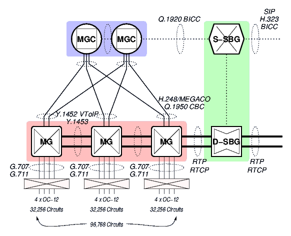
MGC/MGs. (See the MGC and MG arrangement in relation to the S-SBG/D-SBG of Figure 1, page ![[*]](papers/strvoip/crossref.png) .) Some assumptions are as
follows:
.) Some assumptions are as
follows:
- The MGs likely only support G.711, mu-law, with a 20 or 30 millisecond payload.
- The MGCs and MGs likely do not support DTMF and Tone RTP payloads.
- The MGCs likely do not support sophisticated early media (such as the PRACK or UPDATE methods).
Forwarding Requirements
Forwarding needs of VARs can be met with an decomposed or integrated S-SBG (Signalling Session Border Gateway) and D-SBG (Data Session Border Gateway), where the S-SBG acts as an outgoing and incoming SIP proxy and the D-SBG acts as an IP-IP Media Gateway. The positioning of such a gateway is illustrated in Figure 1.
It is fully expected that the integrated S-SBG/D-SBG appliance be capable of completely replacing any SBC (Session Border Controller) equipment at the boundary to the administrative domain.
Transcoding Requirements
The transcoding needs of providers to LTE and WiMAX networks can be met with a decomposed or integrated S-SBG (Signalling Session Border Gateway) and D-SBG (Data Session Border Gateway), where the S-SBG acts as an outgoing and incoming SIP proxy and the D-SBG acts as an IP-IP Media Gateway. The positioning of such a gateway is illustrated in Figure 1.
It is fully expected that the integrated S-SBG/D-SBG appliance be capable of completely replacing any SBC (Session Border Controller) equipment at the boundary to the administrative domain.
Description
The overall solution architecture has been designed and revised may times during the evolution of The OpenSS7 Project. An MG (Media Gateway) stack has been previously defined in detail. The relationship between the STREAMS drivers and modules that make up the MG solution architecture and related components are illustrated in Figure 2. The figure illustrates the software components necessary for implementation of a complete H.248/MEGACO based Media Gateway (MG). The upper level components (that are outside the scope of this document) consist of:
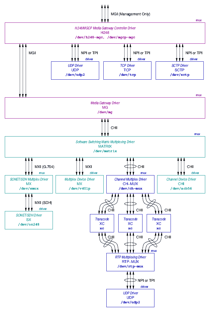
- H.248/MGCP Media Gateway Controller (H248) Driver:
- The H248
drivers is a multiplexing driver that is used to communicate with a remote
Media Gateway Controller (MGC) using H.248/MEGACO over UDP, TCP or SCTP. This
driver parses messages and performs control of the MG Driver that provides the
actual MG function.
Implementing this as a STREAMS driver is not necessary. The XGCP library H.248 stack implementation can be used to affect the same ends. The XGCP library interfaces with the underlying STREAMS UDP, TCP and SCTP pseudo-device drivers; however, the handling of H.248 messages is performed within the library in user-space.
- Media Gateway (MG) Driver:
- The MG driver provides H.248-like
internal control of the software switching matrix and associated media stacks.
It uses the Media Gateway Interface (MGI) (MGI11). It is also
responsible for the generation of tones, playing of audio files, etc; however,
its primary function is to control and manage the software switching
matrix.
Note that rather than directly communicating with the H248 driver; the control of the MG driver can be performed using the XGCP user-space library with a local (instead of remote) context.
- Software Switching Matrix (MATRIX) Multiplexing Driver:
- The
MATRIX implements a software switching matrix that switches media and control
messages between the upper and lower multiplex interfaces.
- Media Stacks:
- The media stacks make up the lower levels of the
architecture. Media stacks exist for PDH, SDH and RTP. (Media stacks also
exist for ATM and VToIP, but are not illustrated.)
The primary component of concern to the current work is the RTP media stack,
shown in insert in Figure 3, page .
SIP Stack
The SIP stack features the sofia SIP libraries. These libraries have
been (or will be) modified for performance as outlined in Section
4.2.3, page .
Note also that to provide abstraction of the control interface to the sofia SIP stack, the XCC XOM-based API can be used instead. The permits swapping the underlying SIP implementation out for some other component at some point. Also, it can provide a homogeneous interface for SIP call control, H.323 call control, ISUP call control, and ISDN call control.
H.248 Stack
There are no stand-along open source H.248 Stack implementations. Erlang provides an open source licensed H.248 Stack, but it requires the entire Erlang environment. Some other projects have integrated H.248 capability but it is meager and not worth propagating. Unfortunately, this means that the OpenSS7 project must develop its own H.248 stack.
The H.248 libraries utilize a XOM-based interface for the generation and receipt of H.248/MEGACO messages called the XGCP. The messages of this interface can be used for the MGC side of H.248 communications, for the MG side of H.248 communications, and for local MG control, depending on the context selected when the API is initialized. Because the identical service interface and API is used both for MGC remote control as well as MG local control, the same interface can be used for both. That is, applications using the XGCP can be made unaware of whether the MG services are local or remote.
This permits, for example, issuing an identical set of requests against a remote mated MG as are requested of the local MG, permitting synchronization of the mated MGs.
MG Stack
The general organization of STREAMS drivers and modules is illustrated in Figure 3. The primary components of the media stack, illustrated in Figure 3, are as follows:
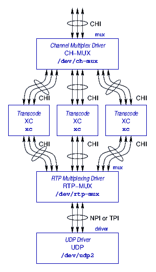
- Channel Multiplex Driver (CH-MUX):
- The channel multiplex driver
(CH-MUX) sits at the top of the forwarding/transcoding media stack. The CH-MUX
is described in more detail in Section 3.3.1, page
.
- Transcode Modules (XC):
- The transcoding modules (XC) are specialized
modules that sit in an interior multiplexed Stream within the media stack. The
XC modules are described in more detail in Section 3.3.2,
page .
- RTP Multiplexing Driver (RTP-MUX):
- The RTP (Real-Time Transport
Protocol) multiplexing driver (RTP-MUX) sits and beneath the transcoding Streams
and provides a switching nexus for dispatching packets to and from the
appropriate transcoding Streams. The RTP-MUX is described in more detail in
Section 3.3.3, page .
- UDP Driver:
- The UDP (User Datagram Protocol) driver sits at the
bottom of the media stack and is responsible for distributing packets to the
network and discriminating packets received from the network. The UDP driver is
described in more detail in Section 3.3.4, page
.
Channel Mutliplexing (CH-MUX) Driver
The channel multiplexing driver sits at the top of the RTP forwarding/transcoding media stack. It provides a Channel Interface (CHI) (CHI11) service interface at the upper boundary. It is responsible for providing control of the RTP forwarding and transcoding performed by the media stack beneath it. This driver has the capability of being interfaced with the Media Gateway Driver (MG), or an upper layer user application that controls the RTP stack.
The CH-MUX driver is responsible for cross-connecting a transcoded media stream between RTP termination points. The media format at the upper interface is audio/pcmu/8000/1, audio/pcma/8000/1 or audio/l16/8000/1.
The CH-MUX driver is also responsible for providing transparent adaptive jitter
buffering of downward data streams. Transparent adaptive jitter buffering is
described in detail in Section 4.3, page
.
Transcoding (XC) Module
The transcoding modules provide all of the heavy lifting (computationally intense operations) necessary for transcoding from the PCMU, PCMA or L16 upstream format, to a specific codec's native downstream format, and vise versa.
The use of STREAMS modules for transcoding provides for several
performance gains: Instruction Cache Acceleration described in Section 4.2.2.1, page ; Pipelining, Section 4.2.2.2, page ; and, Super Scalar Execution, Section 4.2.2.3, page
.
The RTP payload provided from above is not necessarily in sequence and may be
lossy. The RTP payloads provided from below are also not necessarily in
sequence and may also be lossy. The specific XC module is responsible for
sequencing and handling lost payloads as necessarily to the specific encoding or
decoding process. This is performed using a technique called Transparent
Adaptive Jitter Buffering that is detailed in Section
4.3, page .
RTP Multiplexing (RTP-MUX) Driver
The RTP multiplexing driver sits toward the bottom of the RTP forwarding/transcoding media stack. It provides a Channel Interface (CHI) (CHI11) service interface at the upper boundary, and a Network Provider Interface (NPI) (NPI92) service interface at the lower boundary. It is responsible for interfacing the transcoding modules above it to the UDP driver beneath it. It is also responsible for performing RTP forwarding.
The primary function of the RTP-MUX driver is to dispatch RTP packets arriving from the UDP driver to the appropriate decoding stack (transcoding modules).
The RTP-MUX driver is also responsible for providing transparent adaptive jitter
buffering of upward data streams. Transparent adaptive jitter buffering is
described in detail in Section 4.3, page
.
UDP Driver
The UDP driver sits at the bottom of the RTP forwarding/transcoding media stack. It provides a Network Provider Interface (NPI) (NPI92) service interface at the upper boundary and interfaces with Linux networking at the lower (internal) interface. It is responsible for sending and receiving RTP, RTCP and STUN packets to and from the network.
Method
This section describes some of the methods that are used to achieve large scale operation and maximum performance.
Multi-Stream Interfaces
The Multi-Stream Interface technique is used to provide large-scale RTP forwarding and transcoding using STREAMS. Typical STREAMS interfaces such as the Network Provider Interface (NPI) (NPI92) provide a single stream for each network relation (connection between local transport address and remote transport address). While this is suitable for a number of network connections on the order of tens or hundreds, it does not scale under Linux to the thousands, tens of thousands, or even hundreds of thousands. Because the intended scale of the appliance is 10,000 to 500,000 channels of forwarding and transcoding, and because the Linux operating system only supports several thousand open file descriptors system-wide, another approach became necessary.
In an attempt to reuse existing service interfaces such as the Network Provider Interface (NPI), a general approach to converting an existing per-Stream interface to a Multi-Stream Interface was devised. The approach provides a separate device or clone minor that can be opened that provides the multi-Stream interface from the primary device or clone minor that provides the per-Stream interface. Message primitives that are passed on the multi-Stream interface have a 64-bit token prefixed to each message primitive. This 64-bit token identifies the individual virtual Stream within the multi-Stream interface. There are a pair of 64-bit tokens defined: one defined by the user of the service interface; the other by the provider. For the most part, message primitives that are passed from user to provider are prefixed with the provider's tag; message primitives passed from provider to user, the user's tag. However, the first transaction (one that ``opens'' the virtual Stream) has the user tag provided on the user primitive and provider tag on provider primitive. This mechanism provides for the initial exchange of tag values. Tag size was selected at 64-bits to permit either the user or provider to use a memory address as the tag.
For the RTP forwarding/transcoding media stack, all interfaces use the Multi-Stream Interface approach.2
Performance Improvements
Software codecs and transcoding is not a new concept. However, most software codec implementations do not perform well, and the vast majority of implementations are based on dedicated DSP (Digital Signal Processor) hardware.
Product literature available on the web indicates that software codecs and transcoding can only accommodate a maximum of about 1000 channels, and even then only for the less complex or computationally intense codecs. Even dedicated DSP approaches yields only about 1000 to 2000 channels per large form-factor module populated with a DSP farm. Some network processors (NP) appear to provides larger scale implementation; however, costs are high and scalability is still low.
In fitting with the objective of providing transcoding support on a single host of between 10,000 and 500,000 simultaneous channels of G.729/G.711 transcoding, performance improvements over the approaches taken by other software transcoding implementations is necessary.
Disadvantages of Current Approaches
The disadvantages of other software transcoding approaches appear to be as follows:
- Reference implementation. Many transcoding implementations
actually use copies of the ITU-T Reference implementation C-language
code as their implementations. The C-language code reference
implementations were written with correctness and off-line verification in
mind and not any manner of performance.
- Poor scheduling. Because reference implementations of codecs are
designed for off-line verification, they are single-threaded. This results
in poor processor core utilization when used to attempt real-time processing
of multiple channels.
- Context switching. Most software transcoding implementations are
user-space implementations. This causes additional context switches and
scheduling difficulties for each packet transcoded.
- Unpinned memory. As user space implementations base on the
off-line reference implementation, most software transcoding implementations
do not utilize pinned memory (locked memory) and a subject to the whims of
memory swapping.
Advantages of the Proposed Approach
The advantages of the proposed approach are:
- Kernel implementation rather than user space. Performing encoding and
transcoding using the STREAMS framework within the kernel provides for
light-weight process scheduling with a significant reduction in context
switching.3 Also, the STREAMS scheduler schedules light-weight processes
on a different basis that the Linux process scheduler processes
heavy-weight processors or threads, particularly as regards processor
persistence and cache heat. The Linux Fast-STREAMS scheduler promotes
more efficient batch processing, whereas, the main scheduler favours low latency
single-shot execution over batch processing. This is described in more detail
in Section 4.2.2.1, page .
- Utilization of the STREAMS framework.
The STREAMS framework can be used for
This is described in more detail in Section 4.2.2.1, page
and Section 4.2.2.2, page
.
- Utilization of specialized SIMD instruction sets on modern
processors.
This is described in more detail in Section 4.2.2.3, page
.
Instruction Cache Acceleration.
Instruction Cache Acceleration is a byproduct of the STREAMS framework, provided that some design principles are followed when writing STREAMS drivers and modules.
Much ado has been made about data cache heat and efficiency in the Linux operating system; however, general processor design and implementation over the last 20 or 30 years dictates that instruction cache heat and efficiency has a much larger impact on system performance. There are several characteristics of the STREAMS framework that provide for instruction cache efficiency:
- Light Weight Processes:- STREAMS provides the ability to chain
modules and drivers along a Stream to break complex tasks into smaller more
manageable pieces. These modules are independent of each other (execution is
asynchronous), yet without requiring an expensive context switch between
modules.
- Service Procedures:- STREAMS provides the ability to defer
processing of messages until a later point in time. Event driven soft-real-time
systems have the difficulty that event showers can occur, overwhelming the
system. Hard real-time synchronous systems (such as DSP) have the problem that
excess capacity (the processing capacity not needed to meet a deadline) remains
inaccessible. Service procedures in STREAMS cause event showers to be
handled through queuing and flow control. Queuing causes multiple events of a
similar nature to be queued together, so that they can be processed within the
service procedure in a hard loop (without any context switch). This causes
increased instruction (and even data) cache efficiency during event showers,
increasing the stability and efficiency of the system.
- Processor Persistence:- Not really a characteristic of STREAMS, but a characteristic of Linux Fast-STREAMS, processor
persistence is a situation where events scheduled for execution on adjacent
queues, callbacks or call-outs are scheduled on the same processor that invoked
them. While one might think that better performance could be achieved by
scheduling them on any available processor, both data and instruction cache
ping-pong can result unless processor persistence is applied. Also, processor
persistence reduces lock contention on multiprocessor systems. Processor
persistence is also conducive to ``batching'' of messages: when a batch of
messages is being processed in a service procedure that passes messages up or
down stream, those messages will not be processed until the service procedure
returns (completes its batch). This keeps other service procedures from being
scheduled too early, and allows the batch to flow through the STREAMS
framework, increasing instruction and data cache efficiency further.
Considering these characteristics of the STREAMS framework and Linux Fast-STREAMS implementation, several principles can be used in the design of drivers and modules to accelerate instruction cache (and data cache) efficiency, as follows:
- Always provide service procedures except for the most simple of
modules.
Providing service procedures and using them wisely increases the performance
through batch processing, improved instruction cache efficiency, and pipelining.
- Always queue normal priority messages for processing by the service
procedure.
Messages should always be queued quickly for processing by the service
procedure. The only exception is some messages that have to be responded to
immediately (like M_FLUSH), and potentially some messages that terminate
on the module and do not result in messages being passed up or down stream.
- Always process fast-path messages out of the service procedure.
The data fast-path should always be processed out the service procedure for
maximum performance and increased stability in the face of event showers.
- Keep fast-path service loops within the service procedure small and
tight.
Processing of data in the fast-path out of the service procedures should be
small and tight as possible so that instruction cache efficiency can provide
maximum benefits.
- Break long compute-intensive tasks down into smaller units and
pipeline them in a chain of modules.
Breaking larger tasks down into smaller and tighter units chained together in a
stream of modules (pipelining) provides better instruction cache and data cache
efficiency and provides more degrees of freedom and opportunities for multiple
processors to operate along different portions of the stream.
Pipelining.
Pipelining can be achieved by proper organization and interconnection of STREAMS drivers and modules. In general, where functions performed on messages passed (upstream or downstream) differ, a separate Stream should be used for each function.
For example, the IP driver intercepts packets that are bound for the D-SBG function. Packets can be processed as media-aware transcoding, or media-agnostic forwarding. Because these two functions utilize different fast-paths, the IP driver discriminates between the two and passes packets for transcoding to one upper Stream and packets for forwarding to another.
As another example, the RTP module processes RTP packets for transcoding. The
transcoding is always performed between G.711 or 16-bit linear PCM. Because
the functions performed depends on the coding of the RTP payload, the RTP
driver distinguishes between payloads and passed the packets to the
appropriate upper module chain responsible for transcoding that specific
payload. This is illustrated in Figure 3, page
.
Pipelining in this fashion improves both instruction and data cache efficiency by batching together packets upon which like functions are performed in service procedures.
Super Scalar Execution.
Super-scalar execution (SSE) and related processing approaches (MMX, etc.) provide a library accessing special purpose super-scalar execution instructions in modern processors. For the most part these are SIMD (Single Instruction Multiple Data) instructions that provide a 2-wide, 4-wide, or 8-wide data path with a single instruction pipeline. For algorithms that are amenable to these approaches, execution performance can be increased by a factor of the data path width (2, 4 or 8) on a single processor.
Although these approaches are well known, most software codec implementations simply utilize the off-line coded reference implementations of the codecs rather than attempting to optimize them in any way. This, of course, leads to much poorer performance than is possible.
It has been stated that one of the advantages of using DSP over general
purpose RISC or CISC processors is that DSP can retrieve an entire block of
data at the same time and perform operations on that data in parallel. Some
DSP are MIMD (Multiple Instruction Multiple Data) architectures. By utilizing
the SIMD (Single Instruction Multiple Data) capabilities of modern general
purpose processors, and by utilizing pipelining (see Section
4.2.2.2, page ), multiple cores
can be invoked to achieve greater calculation performance than that achievable
using DSPs. This is because digital signal processors often have
significantly lower clock and memory speeds and do not perform caching in the
normal sense: therefore, DSP cannot take advantages of cache acceleration
techniques such as those described under Instruction Cache Acceleration:
Section 4.2.2.1, page .
SIP Implementation
The SIP implementation intended on being used is the sofia SIP stack. The sofia SIP implementation is principally a shared-object library that is used in a main event loop by an application program that implements the SIP state machine. Several performance improvements need to be made to the sofia libraries as follows:
- The sofia code base does not version its symbols. Proper library
versioning needs to be added.
- The sofia code base does not address cancellation points for
threaded programs. Proper cancellation treatment for asynchronous thread
cancellation needs to be added.
- The sofia code base does not organize functions by code heat.
Functions need to be organized by code heat.
- The sofia code base compiles without profiling. The code base
needs to be profiled and branch prediction included in the code base.
- The sofia code base uses Linux sockets for UDP, TCP and
SCTP. The OpenSS7 STREAMS implementations of these are more efficient
and provide a performance increase due to batching and reduced context
switching. The sockets interface to UDP and SCTP need to be substituted for
XTI interface to the OpenSS7 STREAMS implementations of these.
Unfortunately, the libsofia-sip libraries have been added to recent major distributions (such as Debian, Mageia, Fedora), largely in support of the telepathy package. This means that there is little opportunity to properly repackage the library. On the other hand, it may be possible to repackage the library as a different implementation of the same interface with proper library versioning.
Note that the sofia SIP implementation is not a full blown application, but is, rather, a set of libraries and event handlers that can be used to build a SIP application.
Transparent Adaptive Jitter Buffering
Adaptive and non-adaptive jitter buffering is a technique whereby the playback of audio data is buffered and played back as a delayed program in an attempt to alleviate any out of sequence arrival or jitter between inter-arrival times for RTP packets. The normal form of jitter buffering is only performed at the termination of an audio stream and is not as necessary within the network.
For transcoding, most codecs provide some constraints on the ordering of data chunks in the stream and require all adjacent packets before transcoding a given segment can occur. To accommodate transcoding, it is necessary to perform some resequencing and buffering of segments to perform the transcoding function. However, because playback is not being performed, and because most codecs permit segments interior to the data stream to be encoded without consideration for the signal outside the pertinent segment range, some actions performed by normal terminating jitter buffering are not required.
The actions of normal jitter buffering that do not need to be performed to accomplish transcoding are as follows:
- Loss Detection:- The transparent adaptive jitter buffer does not
have to determine when packets are lost by imposing a maximum delay as is
performed with normal jitter buffering.
- Avoiding Early Delivery:- Because playback is not being performed,
transparent adaptive jitter buffering does not have to worry about early
delivery. As soon as a packet is available for transmission, it can be
transmitted regardless of the order in which the packets are processed.
- Equal Payload:- Normal jitter buffering typically requires playback
at a constant rate and requires that each playback segment be of the same size
and delivered synchronous with the playback clock. This is not the case for
transparent adaptive jitter buffering that can coalesce multiple segments into a
larger payload (up to maxptime) to more efficiently utilize the network.
This can help with jitter reduction as well as compensating for network
congestion upstream by reducing packet overheads downstream.
Transparent adaptive jitter buffering works as follows:
- Packet payloads are added to the buffer using an insertion sort.
- When the addition of a packet results in a contiguous segment sufficient
for encoding, a maximally sized segment is struck from the buffer and encoded.
- When an excessive amount of segment fragments exist in the buffer, the
oldest segment fragments that constitute the excess are struck. Depending on
the codec, loss reports might be generated for the struck segments.
- Where one incoming packet maps to an integral number of segments, the
buffer is simply bypassed.
Transparent jitter buffering, therefore, has the following characteristics that are different from normal non-adaptive or adaptive jitter buffering:
- Segments are delivered as soon as they become available.
- Jitter is maintained across the buffer to the greatest extent possible
considering the ordering needs of the encoding.
Note that most implementations perform normal RTP termination instead of adaptive jitter-buffering.
RTCP Packets
When forwarding RTP and RTCP packets, RTCP packets are treated the same as any other UDP packets and are simply IP address and port translated and forwarded. Transcoding, on the other hand, is more complex and requires that RTCP packets be transcoded to some degree as well, particularly as regards SR (Sender Report) and XR (Extended Report) messages.
In the same spirit as adaptive jitter-buffering, the D-SBG is transcoding the RTP stream and is not terminating it. As a result, the adaptive jitter buffering is considered part of the network. RTCP reports are not generated by the transcoding: transmitted RTCP packets are simply 1:1 translated versions of received RTCP packets.
DTMF Digits and Tones
Many low bit-rate (LBR) codecs are incapable of successfully encoding DTMF digits. This is primarily because LBR codecs make assumptions that the media content is voice. Transport of DTMF digits can be performed in two ways: 1), specification of DTMF digits as signalling events using SIP; and, 2), specification of DTMF digits using a, possibly redundant, RTP payload.
From the perspective of forwarding, any RTP stream that is forwarded will also contain DTMF RTP payloads when necessary.
From a transcoding perspective, however, some codecs (e.g. G.711) will carry the DTMF digits in-band; whereas other (e.g. G.729) will carry them out of band using one of the methods above. When transcoding, there is a point at which the out-of-band DTMF digits must be played and mixed in-band; and, a point at which DTMF digits must be detected in-band and converted to out-of-band signals.
For the most part, for the LTE/WiMAX transcoding application, DTMF digits will originate from mobile stations in the mobile network (out-of-band beside G.728 or G.729 codecs) rather than the PSTN. So when transcoding from G.728 or G.729 to G.711 for PSTN use, the out-of-band DTMF digits will have to be played and juxtaposed with the media stream when transcoding from G.729 (for example) to G.711. The question is one of functional placement within the transcoding media stack. Two positions are opportune: at the top of the DTMF digit media transcoding stream before delivering PCMU, PCMA or L16 media data to the top of the CH-MUX multiplexing driver; or, at the top of the G.711 media transcoding stream (on the way down). The former cannot handle DTMF digits out-of-band within the MG driver or application above the CH-MUX; the later can.
Because the MG application or module above the CH-MUX driver must be able to handle DTMF digit events separate from the media stream, it is necessary to choose the second positioning (DTMF digit media generation is handled at the top of the G.711 codec media stack on way down).
In the other direction, the top of the G.711 codec media stack will also require DTMF detection to be performed at the last stage and out-of-band DTMF digit events reported to the top of the CH-MUX and possibly to the MG application or module above. The MG application or module, of course, needs to specify whether DTMF digit detection is required or not, as part of the transcoding of the stream.
Tones, on the other hand, are more likely to originate from the PSTN and require delivery to the LTE/WiMAX network using out-of-band tones. With SS7 connectivity of the carrier's internal MGC/MG complex, however, the MGC should indicate most conditions using SIP signalling rather than attempting to indicate those with in-band tones.
Symmetric RTP
For general purpose RTP handling in the face of NAT and NAPT, the remote IP address and port associated with the RTCP packet stream may be different from the recommendations of RFC 3550.4
There are two ways to handle NAT/NAPT: ICE (ICE10) (using STUN (STU03)) and latching. With ICE, STUN messages are sent by the remote system to the D-SBG's RTP and RTCP ports to determine the appropriate IP addresses and port number for NAT/NAPT traversal. The remote system will then report an appropriate IP address and port combination for RTP and RTCP in the SDP Answer. To accommodate this, the D-SBG should demultiplex and respond appropriately to STUN messages received on the RTP and RTCP ports. ICE/STUN has many problems and impacts post-dial delay and early media and should not be used in gateway scenarios.
With latching, RTP/RTCP streams are only half-formed (have only a local IP address and port number) until a message is received on each port from the remote system. The D-SBG then latches to the source address contained in the first messages received from the remote system. These messages, of course, must pass validation. To accommodate this approach, the D-SBG should support such latching.
Nevertheless, in the configuration most expected for LTE or WiMAX operation, or in the case of VAR RTP forwarding, calls are expected to progress from the S-SBG/D-SBG to an internal MGC/MG network, or pass out over the internet to a remote S-SBG/D-SBG proxy. In both cases, there should be not need for NAT/NAPT. Any NAT/NAPT that needs to be performed is performed by the D-SBG itself.
STUN Packets
Interactive Connectivity Establishment (ICE) is described in RFC 5245 (ICE10). Simple traversal of UDP through NATs (STUN), is described in RFC 3489 (STU03). ICE sends STUN packets to RTP and RTCP ports on remote systems expecting a response. See the RFCs for details. Because STUN responses also need to be sent from UDP addresses and ports different from the normal RTP and RTCP port numbers (to detect full or partial cone), STUN packets need to be demultiplexed at the UDP driver and processed independent of the media stack. This is true for both the forwarding and transcoding scenarios, because STUN packets need to terminate on the D-SBG.
Early Media
As discussed briefly in Section 2.1, page
, the carrier's LTE/WiMAX MGC/MG complex may be
outdated and without warranty. This means that neither software nor hardware
upgrades are necessarily available. Handling of early media by such systems
might be non-optimal. Provisional reliable response and update methods for
early media might not be available. Therefore, the media stack must be
prepared to receive candidate payload as early media. Typically, and for
security considerations, this is likely only internal to the boundary formed
by the S-SBG/D-SBG: that is, facing the legacy MGC/MG complex. External
interconnect can have stricter requirements. Therefore, the media stack, and
in particular the UDP driver at the bottom, must be capable of being
instructed to permit early media on a termination point by termination point
basis.
Note that this issue is related to latching as described in Section 4.6, above.
Redundant Media
Carrier Grade Redundancy
Because the LTE and WiMAX application would typically be housed within a incumbent carrier or CLEC's network, and due to the large scale planned for the device, carrier grade redundancy will likely be necessary. Link failures can easily be accommodated with Ethernet Bonding, or by using APS (Automatic Protection System) for 10Gig Ethernet. Node failures, on the other hand, must be handled by the system architecture and design.
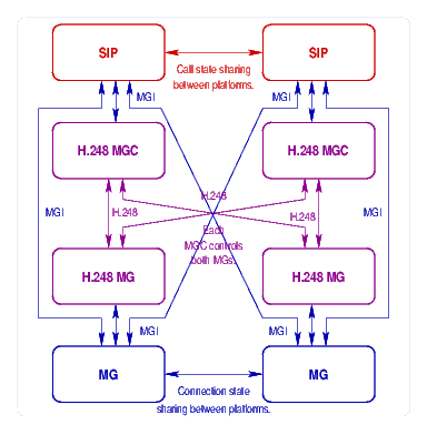
Design for redundancy consists of decomposing the S-SBG and D-SBG functions within the integrated platform, and providing multiple platforms that can handle both functions for any failed platform within the cluster. This can be performed in a 1+1 or N+1 arrangement. A 1+1 arrangement is illustrated in Figure 4, above.
To maintain D-SBG synchronization between mated D-SBG, an H.248 interface can be exposed between mated D-SBG. When the S-SBG function establishes connectivity through the D-SBG, the mated D-SBG can be sent the same connectivity instructions using H.248 over an inter-D-SBG link. SCTP (Stream Control Transmission Protocol) with binary H.248 encoding should be used for this purpose. This synchronization results in a switching matrix with the mated D-SBGs that is identical. To handle D-SBG node failures, then, consists of performing an IP takeover (gratuitous ARP) or APS fail-over between nodes.
Barring the availability of an H.248 interface to the D-SBG (primarily due to the lack of a suitable stack), a custom protocol can be implemented between mated D-SBG. SCTP could also be used for transport of this protocol. The protocol could be a simple transaction update, where a checkpoint state is transmitted between MG implementations. It could also be a simple transport of the MGI interface from one machine to another. The MG implementation used, illustrated in blue in Figure 4, is the OpenSS7 MG Driver. This is a kernel-space STREAMS implementation.
To maintain S-SBG synchronization, a custom protocol can be implemented between mated S-SBG. SCTP could also be used for transport of this protocol. The protocol would be a simple transaction update, where a checkpoint state is transmitted between SIP implementations. The SIP implementation used, illustrated in red in Figure 4, is the sofia SIP stack. This is a user-space SIP implementation.
Redundancy Architecture
Figure 5 illustrates the basic redundancy architecture.
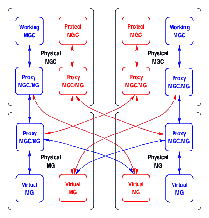
MG Features.
The redundancy architecture has the following MG features:
Virtual MGs (VMG) have a working copy on one physical MG, and a redundant copy on zero or more other physical MGs. A Proxy MGC/MG (MG Cluster Controller, or MGCC) is used either collocated with a physical MG or physical MGC. The MGCC is responsible for acting like a single, reliable, MG toward an MGC, and replicating state across the redundant copies. Virtual MG (VMG) copies normally communicate through the MGCC on the primary (working) physical MG, for that VMG.
MGCs have a working copy on one physical MGC, and a redundant copy on zero or more other physical MGCs. This need not be a full virtual MGC, but can be a partition within the working MGC for the physical MGC. When a physical MG fails, its redundant copy on another physical MG will eventually detect the loss of communications with the working physical MG. Because it loses communication, it attempts to first contact the MGCC at the working MGC. When the communications attempt is successful, the working MGC MGCC will have more information concerning the health of the working physical MG because it either communicates with it or not. When a protect VMG looses communication with the working VMG's MGCC and cannot communicate with the working MGC, it fails over to attempting communications with the protect MGC. Again, the protect MGC will have more information concerning th health of the physical MG containing the working VMG because it either communicates with it or not.
MGC Features.
The redundancy architecture has the following MGC features:
Each MGC cluster has a working copy on one physical MGC, and a redundant copy on zero or more other physical MGC. This need not be a full virtual MGC, but can be a partition within the working MGC for the physical MGC. Working and Protect MGC partitions do not necessarily communicate direct with each other. Some mechanism (such a HACMP IP takeover) is used for switchover of call control sessions (e.g. SIP messaging); however, MEGACO/H.248 service ports are different.
Communications linkages between MGC and MG use SCTP (Stream Control Transmission Protocol) for best link failure detection, multi-homing, flow control, and CMT. Communications linkages between all necessary entities are maintained at all times. This provides an indication of the health of physical MGC/MG entities at the other end of the SCTP association, and some indication of the health of other entities.
MGC do not necessarily have to provide any means for direct state sharing between the on-line (Working) and off-line (Protect) copies of the MGC. Because the MGCs cannot function correctly (except to simply release calls) without a functional MG anyway, MGC checkpoint state is saved on the VMG images using the MGC information package.(MEG06).
Unfortunately, the MGC information package will only store 128 octets per termination, meaning that complete session state information (aside from what information is already stored on the MG) must be contained within 256 octets. Also, 128 octets of information can be saved on the root termination. This information could contain information about the last active VMG.
MGC Failover.
When the Working MGC failure is detected by the Protection MGC, the MGC perform whatever IP takeover is necessary to acquire all of the SIP communications that was destined for the old system. In addition, the Protect MGC begins to initiate actions necessary to assume control of the associated VMG.
Because each MGC expects to have SCTP associations formed for communications at all times (regardless of the ServiceChange state of the MG), the Protection MGC can easily determine whether the various VMG images are accessible. Further, when a VMG registers with the Protection MGC, additional information can be determined from the ServiceChangeMethod, which is one of:
- Graceful: indicates that the specified terminations will be taken
out of service after the specified service change delay; established
connections are not yet affected, but the MGC should refrain from establishing
new connections and should attempt to gracefully tear down existing
connections on the termination(s) affected by the service change command. The
MG should set the termination's service state at the expiry of the service
change delay or the removal of the termination from the active context
(whichever is first), to ``out of service.''
- Forced: indicates that the specified terminations were taken
abruptly out of service and any established connections associated with them
may be lost. For non-Root terminations, the MGC is responsible for cleaning
up the context (if any) with which the failed termination is associated. At a
minimum, the terminations shall be subtracted from the context. The
termination's service state should be ``out of service''. For the root
termination, the MGC can assume that all connections are lost on the MG and
thus can consider that all terminations have been subtracted.
- Restart: Indicates that service will be restored on the specified
terminations after expiration of the service change delay. The service state
should be set to in-service upon expiry of the service change delay.
- Disconnected: always applied with the root termination identifier,
indicates that the MG lost communication with the MGC, but it was subsequently
restored to the same MGC (possibly after trying other MGCs on a
pre-provisioned) list). Since MG state may have changed, the MGC may wish to
use the Audit command to resynchronize its state with the MG's.
- Handoff: sent from the MGC to the MG, this reason indicates that the
MGC is going out of service and a new MGC association must be established.
Sent from the MG to the MGC, this indicates that the MG is attempting to
establish a new association in accordance with a Handoff received from the MGC
with which it was previously associated.
- Failover: sent from the MG to MGC to indicates the primary MG is
out of service and secondary MG is taking over. This service change method
is also sent from the MG to the MGC when the MG detects that MGC has failed.
- (Other mutually understood value):
Change-over of VMG.
H.248.1(MEG05) says that an MG will attempt to contact the primary MGC, and then the secondary list in turn until it registers with an MGC. This is not a good way to provide carrier grade redundancy. The VMGs will attempt to register with all MGCs, and will maintain registration with each. If communications should be lost with an MGC, the VMG will attempt to reestablish communications until it is successful. If it should receive a hand-off from an MGC, it will still maintain communications with that MGC. The MG will persist in forming SCTP associations with all MGC. The inability to form an SCTP association between an MG and any of the MGCs will be deemed a failure of the MGC.
Cold Start.
The following steps are taken by an MGC upon registration with an MG:
- Each MGC image will alway accept establishment of a control association
with each of the VMG images.
- On an intial (cold start) of a VMG, the VMG will register with service
change method `Restart.' When the MGC is the active MGC image, and there
is an active VMG image registered, the MGC will begin synchronizing state with
the cold starting VMG image to bring it from cold-standby to hot-standby. The
standby status of the VMG remains cold-standby until this process completes,
and then it moves to hot-standby. When the MGC is a protecting image, no
further action is taken.
- If a VMG should become disconnected from an MGC, it will reconnect and
register with service change method `Disconnected'. When the MGC is the
active MGC image, the MGC will begin synchronizing state between the MGC and
the MG by applying all updates that occurred during the period of loss of
communication (typically only the release of sessions that could not be
released during the control association outage). This is the case regardless
of whether the VMG image was active or standby. During the resynchronization
process, the standby status of a protection VMG is cold-standby. After
synchronization the protecting VMG moves to hot-standby status. If the VMG
was active and is still the active image, it will be marked with an
availability status of degraded. When the MGC is a protecting image, no
further action is taken.
Fail Over.
When the MG detects a failure, the MG can send service changes on the root terminations to indicate the failure as follows:
- The MG, when it detects the failure of the active MG, will send a
service change on the root termination with method `Failover' to the
active MGC. The service change address will identify the failed MG. The MGC
may have already detected failure of the identified MG through other means
(e.g. the loss of an SCTP association or control association to the identified
MG). If the VMG was in cold-standby (active synchronization), the VMG will
move on-line with a degraded availability status.
- The MG, when it detects the failure of the active MGC, will send a
service change on the root termination with method `Failover' to the
standby MGC. The service change address will identify the failed MGC. The
MGC may have already detected failure of the identified MGC through other
means (e.g. HACMP hearbeat). The MGC will begin state synchronization with
the MG to recover MGC state with the VMG. When the VMG is a standby VMG, the
MGC will prefer to synchronize with the active VMG image instead of its
standby images. The standby status of the MGC will be cold-standby prior to
this event, and will move to providing-service.
Switch Over.
Manual or forced switch-over from an active MG to a protecting MG is performed for a number of reasons. The most common reason is for maintenance activity on the working MG, such as hardware or software upgrades. Manual switch-over from an active MG is performed local to the element (at the EMS), or from a management station (NMS). The Optranex10G supports both. Switch over invoked by NMS is performed using SNMP.
A given physical MG will typically be provisioned with working VMG images as well as protection VMG images. Switch-over is only applicable to the working images, whereas, lock-out is applicable to the protection images, (see Section 4.10.1.3.4).
Although all control associations are established and maintained at all times, the MG can send service changes on the root termination to indicate switch-over conditions as follows:
- When a manual or forced switch-over is invoked on an active VMG, the
active VMG will send a service change on the root termination with service
method `Handoff' and the service change address of the MG to which the
switchover should occur. The MGC may accept or refuse the switch-over by its
response (error or success). Some reasons for refusing the switch-over are:
the VMG to which to switch has a cold-standby standby status instead of
hot-standby (it is in the process of being synchronized); or, the VMG is not
currently accessible to the MGC.
Lock Out.
Lock out is a condition that is used instead of switch-over for a protecting VMG. That is, to lock out an off-line, protection VMG image. The locked out condition keep other VMG and MGC from switching to the protection VMG image. Again, the most common reason for lock out is for maintenance activity on the protection MG, such as hardware or software upgrades. Lock out of a standby MG is performed local to the element (at the EMS), or from a management station (NMS). The Optranex10G supports both; however, the local EMS uses the same SNMP interface as the management station (NMS).
A given physical MG will typically be provisioned with working VMG images as well as protection VMG images. Lock out is only applicable to the protection images, whereas, switch-over is applicable to the working images, (see Section 4.10.1.3.3).
To indicate that it is requesting lock-out, an MG may send a service change on the root termination to the MGC to indicate lock-out conditions as follows:
- When a manual or forced lock-out is invoked on an active VMG, the active
VMG will send a service change on the root termination with service method
`Handoff' and the service change address of the active MG (if it is
known, otherwise no service change address). The MGC may accept or refuse the
lock-out by its response (error or success). Some reasons for refusing the
switch-over are: the VMG to be locked out is the only VMG that is
synchronized with the MGC; or, no other VMG is accessible.
Shut Down.
At some times it may be necessary to shut down parts or all of a VMG. This can be invoked at the MG using local EMS or remotely via NMS. A service change command is sent to all MGC to indicate the shut down condition as follows:
- Shutdown of part of all of a VMG (all images) is performed using the
administrative state of the terminations invoked. Shutting down the entire
VMG (all images) can be graceful or forced.5
- For a abortive shutdown of all or part of the VMG (all images), a
service change on the appropriate terminations with service change method
`Forced' is performed. For a graceful shutdown of all or part of the
VMG (all images), a service change on the appropriate terminations with
service change method `Graceful' is performed.
Change-over of MGC.
Partitioned systems.
Difficulties can, of course, occur with a completely partitioned system. That is, if the system in Figure 5 has its communications network severed vertically down the middle. Therefore, some reliable mechanism must be provided to maintain reliable communication across the vertical that will indicate the health of each partition to the other.
MEGACO/H.248 Considerations
A MEGAGO/H.248 stack(MEG05) is implemented in accordance with ITU-T Recommendation H.248.1 (09/2005) and a number of packages. The basic profile is the D-SBG profile specified by ETSI(BGF06) and the MSF:(MSF07) ETSI ES 283 018 version 2.6.7.
Ephemeral Termination Points
The SBG is an IP-IP gateway. Ephemeral termination points are normally chosen by the D-SBG. The S-SBG only specifies the IP realm or group (e.g. `ip/<group>/$'); however, for redundancy purposes, it is necessary for the MG cluster controller to be able to synchronize context state in redundant Virtual MGs. Therefore, ephemeral terminations will by given an orderly naming that specifies the IP interface, address and port combination. The SBG profile requires that D-SBG label terminations `ip/<group>/<interface>/<id>', so for our purposes, termination points will be labelled `ip/<realm>/<interface>/<addrindex>/<port>'. This way the S-SBG can request `ip/<realm>/$', or simply `$' with a `ipr=<realm>' in the termination point descriptor. Once the active D-SBG image chooses an IP address and port number, it returns the termination point identifier `ip/<realm>/<interface>/<addrindex>/<port>' which can be used to establish the identical context on the protecting D-SBG images.
Invoking Forwarding vs. Transcoding
As illustrated in Figure 2 and 3, RTP forwarding is performed at a different level in the OpenSS7 media stack than RTP transcoding. This is because RTP forwarding is media-unaware, media-transparent and media-neutral; does not require termination of RTP media streams, and can most efficiently be handled directly at the UDP driver.
Usage Record Collection
For usage record collection for billing, it likely that the carrier's existing MGC/MG solution provides sufficient usage record collection for the purposes of billing. Nevertheless, antiquated MGC/MG networks likely do not provide all of the mechanisms necessary for performing interconnect reconciliation. Therefore, the S-SBG/D-SBG appliance should provide a mechanism for usage record collection for the purposes of interconnect reconciliation and operational measurements and OSS.
VARs, on the other hand, likely have usage record collection adequate for both billing and reconciliation on their more modern MGC/MG configurations. Therefore, for the forwarding application, it is not necessary to perform usage record collection for the purpose of reconciliation. Nevertheless, usage record collection should be performed for the purpose of operational measurements and OSS.
Results
Analysis
Conclusions
Future Work
Related Work
Acronyms and Abbreviations
The following acronyms and abbreviations are used throughout this document.
| ANSI | American National Standards Institute |
| APS | Automatic Protection Switching |
| ARP | Address Resolution Protocol |
| CHI | Channel Interface (CHI11) |
| CLEC | Competitive Local Exchange Carrier |
| D-SBG | Data SBG |
| DSP | Digital Signal Processor |
| DTMF | Dual Tone Multi-Frequency |
| EIA | Electronics Industry Association |
| ETSI | European Telecommunications Standards Institute |
| GSM | General Services Mobile |
| ICE | Interactive Communications E... |
| IP | Internet Protocol |
| ITU | International Telecommunications Union |
| ITU-T | ITU Telecommunications Sector |
| LBR | Low Bit-Rate |
| LTE | Long Term Evolution |
| MEGACO | Media Gateway Control |
| MG | Media Gateway |
| MGC | Media Gateway Controller |
| MGCP | Media Gateway Control Protocol |
| NAPT | Network Address and Port Translation |
| NAT | Network Address Translation |
| NPI | Network Provider Interface (NPI92) |
| OSS | Operational Support System |
| PCM | Pulse Code Modulation |
| PCMA | PCM A-Law |
| PCMU | PCM mu-Law |
| PSTN | Public Switched Telephone Network |
| RTCP | Real-Time Transport Control Protocol |
| RTP | Real-Time Transport Protocol |
| S-SBG | Signalling SBG |
| SBG | Session Border Gateway |
| SCTP | Stream Transmission Control Protocol |
| SDP | Session Description Protocol |
| SIMD | Single Instruction Multiple Data |
| SIP | Session Initiation Protocol |
| SR | Sender Report |
| SS7 | Signalling System No. 7 |
| SSE | Super Scalar Execution |
| STUN | Simple Traversal of UDP through NATs |
| TIA | Telecommunications Industry Association |
| UDP | User Datagram Protocol |
| VAR | Value Added Reseller |
| XR | Extended Report |
Bibliography
- BGF06
-
H.248 Profile for controlling Border Gateway Functions (BGF) in the
Resource and Admission Control Subsystem (RACS); Protocol
Specification.
ETSI Standard ES 283 018, European Telecommunications Standards Institute, June 2006.
- CHI11
-
Channel Interface (CHI) Specification.
Interface Specification CHI Revision 1.1.2, The OpenSS7 Project, Edmonton, Alberta, July 4 2011.
http://www.openss7.org/.
- ICE10
-
Interactive Connectivity Establishment (ICE): A Protocol for
Network Address Translator (NAT) Traversal for Offer/Answer
Protocols.
RFC 5245, The Internet Society, April 2010.
http://www.ietf.org/.
- MEG05
-
Gateway control protocol: Version 3.
ITU-T Recommendation H.248.1, Iternational Telecommunications Union, Telecom Sector, September 2005.
- MEG06
-
Gateway control protocol: MGC information package.
ITU-T Recommendation H.248.45, Iternational Telecommunications Union, Telecom Sector, May 2006.
- MGI11
-
Media Gateway Interface (MGI) Specification.
Interface Specification MGI Revision 1.1.2, The OpenSS7 Project, Edmonton, Alberta, July 4 2011.
http://www.openss7.org/.
- MSF07
-
S-SBG/P-CSC to D-SBG Interface Implementation Agreement; H.248
Profile for Distributed Session Border Gateways.
Implementation Agreement MSF-IA-MEGACO.009-FINAL, MultiService Forum, September 2007.
- NPI92
-
Network Provider Interface (NPI) Specification, Revision 2.0.0.
Technical Specification, UNIX International, Inc., Parsippany, New Jersey, August 17 1992.
http://www.openss7.org/docs/npi.pdf.
- STU03
-
Simple Traversal of User Datagram Protocol (UDP) Through
Network Address Translators (NATs).
RFC 3489, The Internet Society, March 2003.
http://www.ietf.org/.
Examples
Footnotes
- ... Bidulock1
- bidulock@openss7.org
- ... approach.2
- Note that this Multi-Stream Interface approach is quite applicable to any situation where management of multiplexing drivers become difficult due to the need to dynamically allocate lower stream resources.
- ... switching.3
- Here ``context switching'' is not just the switch in processor context, but the also the penalty incurred by cache misses and lock contention.
- ... 3550.4
- RFC 3550 states that the RTCP port number should be odd and one higher than the corresponding RTP port number, and with the same IP address. This is not necessarily the case when NAT and NAPT middle-boxes exist in the path.
- ... forced.5
- Graceful shutdown is performed by setting the administrative state to shutting-down; forced shutdown is performed by setting the administrative state to locked.
Brian F. G. Bidulock 2014-10-26
Copyright © 2014 OpenSS7 Corporation All Rights Reserved.