| ||
| ||
| ||
| ||
| ||
|
DLPI Documentation
Description: OpenSS7 Project Library Transport DLPI
A PDF version of this document is available here.
Data Link Provider Interface
Data Link Provider Interface Specification
About This Manual
This is Edition 7.20141001, last updated 2014-10-25, of The Data Link Provider Interface Specification, for Version 1.1 release 7.20141001 of the OpenSS7 package.
1 Introduction
This document specifies a STREAMS kernel-level instantiation of the ISO Data Link Service Definition DIS 88861 and Logical Link Control DIS 8802/2 (LLC)2. Where the two standards do not conform, DIS 8886 prevails.
The Data Link Provider Interface (DLPI) enables a data link service user to access and use any of a variety of conforming data link service providers without special knowledge of the provider’s protocol. Specifically, the interface is intended to support X.25 LAPB, BX.25 level 2, SDLC, ISDN LAPD, Ethernet(TM), CSMA/CD, FDDI, token ring, token bus, and Bisync. Among the expected data link service users are implementations of the OSI network layer and SNA path control.
The interface specifies access to data link service providers, and does not define a specific protocol implementation. Thus, issues of network management, protocol performance, and performance analysis tools are beyond the scope of this document and should be addressed by specific implementations of a data link provider. However, accompanying each provider implementation should be information that describes the protocol-specific behavior of that provider. Currently, there are plans to come up with a set of implementor’s agreements/guidelines for common data link providers. These agreements will address issues such as DLSAP address space, subsequent addresses, PPA access and control, QoS, supported services, etc.
This specification assumes the reader is familiar with OSI Reference Model[4] terminology, OSI Data Link Services, and STREAMS.
1.1 Document Organization
This specification is organized as follows:
- Model of the Data Link Layer, presents background on the structure of the data link layer of the OSI Reference Model, and explains the intended architecture in the STREAMS environment. Data link addressing concepts are also presented.
- DLPI Services, presents an overview of the services provided by DLPI.
- DLPI Primitives, describes the detailed syntax and semantics of each DLPI primitive that crosses the data link interface.
- Quality of Data Link Service, describes the quality-of-service parameters supported by DLPI and the rules for negotiating/selecting the values of those parameters.
- Optional Primitives to perform Essential Management Functions, optional primitives to perform certain essential management functions.
- Allowable Sequence of DLPI Primitives, describes the allowable sequence of DLPI primitives that may be issued across the interface.
- Precedence of DLPI Primitives, presents a summary of the precedence of DLPI primitives as they are queued by the DLS provider and/or DLS user.
- Glossary of DLPI Terms and Acronyms, presents a Glossary of DLPI Terms and Acronyms.
- Guidelines for Protocol Independent DLS Users, summarizes guidelines a DLS user implementation must follow to be fully protocol-independent.
- Required Information for DLS Provider-Specific Addenda, presents the information that should be documented for each DLS provider implementation.
- DLPI Header File, presents the header file containing DLPI structure and constant definitions needed by a DLS user or provider implemented to use the interface.
2 Model of the Data Link Layer
The data link layer (layer 2 in the OSI Reference Model) is responsible for the transmission and error-free delivery of bits of information over a physical communications medium.
The model of the data link layer is presented here to describe concepts that are used throughout the specification of DLPI. It is described in terms of an interface architecture, as well as addressing concepts needed to identify different components of that architecture. The description of the model assumes familiarity with the OSI Reference Model.
2.1 Model of the Service Interface
Each layer of the OSI Reference Model has two standards:
- one that defines the services provided by the layer, and
- one that defines the protocol through which layer services are provided.
DLPI is an implementation of the first type of standard. It specifies an interface to the services of the data link layer. The following figure depicts the abstract view of DLPI.
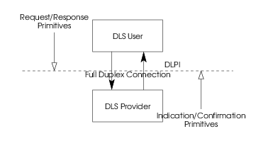
The data link interface is the boundary between the network and data link layers of the OSI Reference Model. The network layer entity is the user of the services of the data link interface (DLS user), and the data link layer entity is the provider of those services (DLS provider). This interface consists of a set of primitives that provide access to the data link layer services, plus the rules for using those primitives (state transition rules). A data link interface service primitive might request a particular service or indicate a pending event.
To provide uniformity among the various UNIX system networking products, an effort is underway to develop service interfaces that map to the OSI Reference Model. A set of kernel-level interfaces, based on the STREAMS development environment, constitute a major portion of this effort. The service primitives that make up these interfaces are defined as STREAMS messages that are transferred between the user and provider of the service. DLPI is one such kernel-level interface, and is targeted for STREAMS protocol modules that either use or provide data link services. In addition, user programs that wish to access a STREAMS-based data link provider directly may do so using the putmsg(2s) and getmsg(2s) system calls.
Referring to the abstract view of DLPI (Figure 1), the DLS provider is configured as a STREAMS driver, and the DLS user accesses the provider using open(2s) to establish a stream to the DLS provider. The stream acts as a communication endpoint between a DLS user and the DLS provider. After the stream is created, the DLS user and DLS provider communicate via the messages presented later in this specification.
DLPI is intended to free data link users from specific knowledge of the characteristics of the data link provider. Specifically, the definition of DLPI hopes to achieve the goal of allowing a DLS user to be implemented independent of a specific communications medium. Any data link provider (supporting any communications medium) that conforms to the DLPI specification may be substituted beneath the DLS user to provide the data link services. Support of a new DLS provider should not require any changes to the implementation of the DLS user.
2.2 Modes of Communication
The data link provider interface supports three modes of communication: connection, connectionless and acknowledged connectionless. The connection mode is circuit-oriented and enables data to be transferred over a pre-established connection in a sequenced manner. Data may be lost or corrupted in this service mode, however, due to provider-initiated resynchronization or connection aborts.
The connectionless mode is message-oriented and supports data transfer in self-contained units with no logical relationship required between units. Because there is no acknowledgment of each data unit transmission, this service mode can be unreliable in the most general case. However, a specific DLS provider can provide assurance that messages will not be lost, duplicated, or reordered.
The acknowledged connectionless mode provides the means by which a data link user can send data and request the return of data at the same time. Although the exchange service is connectionless, in-sequence delivery is guaranteed for data sent by the initiating station. The data unit transfer is point-to-point.
2.2.1 Connection-mode Service
The connection-mode service is characterized by four phases of communication: local management, connection establishment, data transfer, and connection release.
2.2.1.1 Local Management
This phase enables a DLS user to initialize a stream for use in communication and establish an identity with the DLS provider.
2.2.1.2 Connection Establishment
This phase enables two DLS users to establish a data link connection between them to exchange data. One user (the calling DLS user) initiates the connection establishment procedures, while another user (the called DLS user) waits for incoming connect requests. The called DLS user is identified by an address associated with its stream (as will be discussed shortly).
A called DLS user may either accept or deny a request for a data link connection. If the request is accepted, a connection is established between the DLS users and they enter the data transfer phase. For both the calling and called DLS users, only one connection may be established per stream. Thus, the stream is the communication endpoint for a data link connection. The called DLS user may choose to accept a connection on the stream where it received the connect request, or it may open a new stream to the DLS provider and accept the connection on this new, responding stream. By accepting the connection on a separate stream, the initial stream can be designated as a listening stream through which all connect requests will be processed. As each request arrives, a new stream (communication endpoint) can be opened to handle the connection, enabling subsequent requests to be queued on a single stream until they can be processed.
2.2.1.3 Data Transfer
In this phase, the DLS users are considered peers and may exchange data simultaneously in both directions over an established data link connection. Either DLS user may send data to its peer DLS user at any time. Data sent by a DLS user is guaranteed to be delivered to the remote user in the order in which it was sent.
2.2.1.4 Connection Release
This phase enables either the DLS user, or the DLS provider, to break an established connection. The release procedure is considered abortive, so any data that has not reached the destination user when the connection is released may be discarded by the DLS provider.
2.2.2 Connectionless-mode Service
The connectionless mode service does not use the connection establishment and release phases of the connection-mode service. The local management phase is still required to initialize a stream. Once initialized, however, the connectionless data transfer phase is immediately entered. Because there is no established connection, however, the connectionless data transfer phase requires the DLS user to identify the destination of each data unit to be transferred. The destination DLS user is identified by the address associated with that user (as will be discussed shortly).
Connectionless data transfer does not guarantee that data units will be delivered to the destination user in the order in which they were sent. Furthermore, it does not guarantee that a given data unit will reach the destination DLS user, although a given DLS provider may provide assurance that data will not be lost.
2.2.3 Acknowledged Connectionless-mode Service
The acknowledged connectionless mode service also does not use the connection establishment and release phases of the connection-mode service. The local management phase is still required to initialize a stream. Once initialized, the acknowledged connectionless data transfer phase is immediately entered.
Acknowledged connectionless data transfer guarantees that data units will be delivered to the destination user in the order in which they were sent. A data link user entity can send a data unit to the destination DLS User, request a previously prepared data unit from the destination DLS User, or exchange data units.
2.3 DLPI Addressing
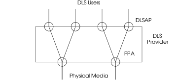
Each user of DLPI must establish an identity to communicate with other data link users. This identity consists of two pieces. First, the DLS user must somehow identify the physical medium over which it will communicate. This is particularly evident on systems that are attached to multiple physical media. Second, the DLS user must register itself with the DLS provider so that the provider can deliver protocol data units destined for that user. The following figure illustrates the components of this identification approach, which are explained below.
2.3.1 Physical Attachment Identification
The physical point of attachment (PPA in Figure 2) is the point at which a system attaches itself to a physical communications medium. All communication on that physical medium funnels through the PPA. On systems where a DLS provider supports more than one physical medium, the DLS user must identify which medium it will communicate through. A PPA is identified by a unique PPA identifier . For media that support physical layer multiplexing of multiple channels over a single physical medium (such as the B and D channels of ISDN), the PPA identifier must identify the specific channel over which communication will occur.
Two styles of DLS provider are defined by DLPI, distinguished by the way they enable a DLS user to choose a particular PPA. The style 1 provider assigns a PPA based on the major/minor device the DLS user opened. One possible implementation of a style 1 driver would reserve a major device for each PPA the data link driver would support. This would allow the STREAMS clone open feature to be used for each PPA configured. This style of provider is appropriate when few PPAs will be supported.
If the number of PPAs a DLS provider will support is large, a style 2 provider implementation is more suitable. The style 2 provider requires a DLS user to explicitly identify the desired PPA using a special attach service primitive. For a style 2 driver, the open(2s) creates a stream between the DLS user and DLS provider, and the attach primitive then associates a particular PPA with that stream. The format of the PPA identifier is specific to the DLS provider, and should be described in the provider-specific addendum documentation.
DLPI provides a mechanism to get and/or modify the physical address. The primitives to handle these functions are described in Optional Primitives to perform Essential Management Functions. The physical address value can be modified in a post-attached state. This would modify the value for all streams for that provider for a particular PPA. The physical address cannot be modified if even a single stream for that PPA is in the bound state.
The DLS User uses the supported primitives (DL_ATTACH_REQ,
DL_BIND_REQ, DL_ENABMULTI_REQ, DL_PROMISCON_REQ) to define
a set of enabled physical and SAP address components on a per Stream basis. It
is invalid for a DLS Provider to ever send upstream a data message for which the
DLS User on that stream has not requested. The burden is on the provider to
enforce by any means that it chooses, the isolation of SAP and physical address
space effects on a per-stream basis.
2.3.2 Data Link User Identification
A data link user’s identity is established by associating it with a data link service access point (DLSAP), which is the point through which the user will communicate with the data link provider. A DLSAP is identified by a DLSAP address.
The DLSAP address identifies a particular data link service access
point that is
associated with a stream (communication endpoint). A bind service primitive
enables a DLS user to either choose a specific DLSAP by specifying its
DLSAP address, or to determine the DLSAP associated with a
stream by retrieving the bound DLSAP address. This DLSAP
address can then be used by other DLS users to access a specific DLS user. The
format of the DLSAP address is specific to the DLS provider, and
should be described in the provider-specific addendum documentation. However,
DLPI provides a mechanism for decomposing the DLSAP address into
component pieces. The DL_INFO_ACK primitive returns the length of the
SAP component of the DLSAP address, along with the total length of the
DLSAP address.
Certain DLS Providers require the capability of binding on multiple
DLSAP addresses. This can be achieved through subsequent binding of
DLSAP addresses. DLPI supports peer and hierarchical binding of
DLSAPs. When the User requests peer addressing, the DLSAP specified
in a subsequent bind may be used in lieu of the DLSAP bound in the
DL_BIND_REQ. This will allow for a choice to be made between a number of
DLSAPs on a stream when determining traffic based on DLSAP values. An
example of this would be to specify various ether_type values as DLSAPs. The
DL_BIND_REQ, for example, could be issued with ether_type value of IP,
and a subsequent bind could be issued with ether type value of ARP. The
Provider may now multiplex off of the ether_type field and allow for either IP
or ARP traffic to be sent up this stream.
When the DLS User requests hierarchical binding, the subsequent bind will
specify a DLSAP that will be used in addition to the DLSAP
bound using a DL_BIND_REQ. This will allow additional information to be
specified, that will be used in a header or used for de-multiplexing. An
example of this would be to use hierarchical bind to specify the OUI
(Organizationally Unique Identifier) to be used by SNAP.
If a DLS Provider supports peer subsequent bind operations, the first SAP that is bound is used as the source SAP when there is ambiguity.
DLPI supports the ability to associate several streams with a single DLSAP, where each stream may be a unique data link connection endpoint. However, not all DLS providers can support such configurations because some DLS providers may have no mechanism beyond the DLSAP address for distinguishing multiple connections. In such cases, the provider will restrict the DLS user to one stream per DLSAP.
2.4 The Connection Management Stream
The earlier description of the connection-mode service assumed that a DLS user bound a DLSAP to the stream it would use to receive connect requests. In some instances, however, it is expected that a given service may be accessed through any one of several DLSAPs. To handle this scenario, a separate stream would be required for each possible destination DLSAP, regardless of whether any DLS user actually requested a connection to that DLSAP. Obvious resource problems can result in this scenario.
To obviate the need for tying up system resources for all possible destination utility is defined in DLPI. A management stream is one that receives any connect requests that are not destined for currently bound DLSAPs capable of receiving connect indications. With this mechanism, a special listener can handle incoming connect requests intended for a set of DLSAPs by opening a connection management stream to the DLS provider that will retrieve all connect requests arriving through a particular PPA. In the model, then, there may be a connection management stream per PPA.
3 DLPI Services
The various features of the DLPI interface are defined in terms of the services provided by the DLS provider, and the individual primitives that may flow between the DLS user and DLS provider.
The data link provider interface supports three modes of service: connection, connectionless and acknowledged connectionless. The connection mode is circuit-oriented and enables data to be transferred over an established connection in a sequenced manner. The connectionless mode is message-oriented and supports data transfer in self-contained units with no logical relationship required between units. The acknowledged connectionless mode is message-oriented and guarantees that data units will be delivered to the destination user in the order in which they were sent. This specification also defines a set of local management functions that apply to all modes of service.
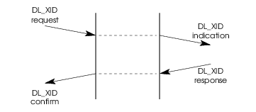
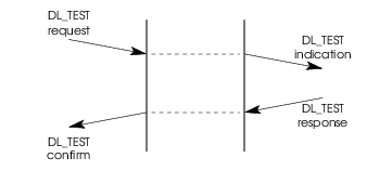
The XID and TEST services that are supported by DLPI are listed below. The DLS User can issue an XID or TEST request to the DLS Provider. The Provider will transmit an XID or TEST frame to the peer DLS Provider. On receiving a response, the DLS Provider sends a confirmation primitive to the DLS User. On receiving an XID or TEST frame from the peer DLS Provider, the local DLS Provider sends up an XID or TEST indication primitive to the DLS User. The User must respond with an XID or TEST response frame to the Provider.
The services are tabulated below and described more fully in the remainder of this section.
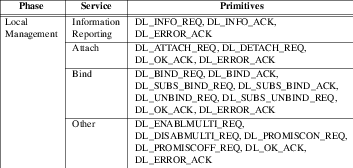
3.1 Local Management Services
The local management services apply to the connection, connectionless and acknowledged connectionless modes of transmission. These services, which fall outside the scope of standards specifications, define the method for initializing a stream that is connected to a DLS provider. DLS provider information reporting services are also supported by the local management facilities.
3.1.1 Information Reporting Service
This service provides information about the DLPI stream to the DLS user. The
message
DL_INFO_REQ
requests the DLS provider to return operating information about the stream. The
DLS provider returns the information in a
DL_INFO_ACK
message.

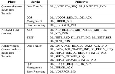
3.1.2 Attach Service
The attach service assigns a physical point of attachment (PPA) to a
stream. This service is required for style 2 DLS providers (see Physical Attachment Identification) to specify the physical medium over which
communication will occur. The DLS provider indicates success with a
DL_OK_ACK; failure with a DL_ERROR_ACK. The normal message
sequence is illustrated in the following figure.
A PPA may be disassociated with a stream using the
DL_DETACH_REQ. The normal message sequence is illustrated in the
following figure.

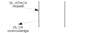
3.1.3 Bind Service
The bind service associates a data link service access point (DLSAP) with a stream. The DLSAP is identified by a DLSAP address.
DL_BIND_REQ requests that the DLS provider bind a DLSAP to a
stream. It also notifies the DLS provider to make the stream active with
respect to the DLSAP for processing
connectionless and acknowledged connectionless data transfer and connection
establishment requests. Protocol-specific actions taken during activation
should be described in DLS provider-specific addenda.
The DLS provider indicates success with a DL_BIND_ACK; failure with a
DL_ERROR_ACK.
Certain DLS providers require the capability of binding on multiple
DLSAP addresses. DL_SUBS_BIND_REQ provides that added
capability. The DLS provider indicates success with a DL_SUBS_BIND_ACK;
failure with a DL_ERROR_ACK. The normal flow of messages is illustrated
in the following figure.
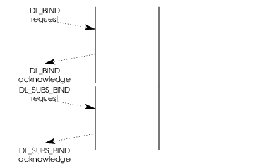
DL_UNBIND_REQ requests the DLS provider to unbind all DLSAP(s)
from a stream. The DL_UNBIND_REQ also unbinds all the subsequently bound
DLSAPs that have not been unbound. The DLS provider indicates success with a
DL_OK_ACK; failure with a DL_ERROR_ACK.
DL_SUBS_UNBIND_REQ requests the DLS Provider to unbind the subsequently
bound DLSAP. The DLS Provider indicates success with a
DL_OK_ACK; failure with a DL_ERROR_ACK.
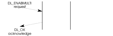
DL_ENABMULTI_REQ requests the DLS Provider to enable specific multicast
addresses on a per stream basis. The Provider indicates success with a
DL_OK_ACK; failure with a DL_ERROR_ACK.
DL_DISABMULTI_REQ requests the DLS Provider to disable specific multicast
addresses on a per Stream basis. The Provider indicates success with a
DL_OK_ACK; failure with a DL_ERROR_ACK.

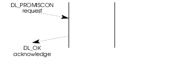
DL_PROMISCON_REQ requests the DLS Provider to enable promiscuous mode on
a per Stream basis, either at the physical level or at the SAP level. The
Provider indicates success with a DL_OK_ACK; failure with a
DL_ERROR_ACK.
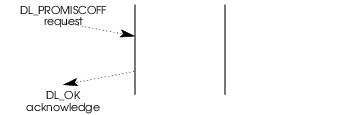
DL_PROMISCOFF_REQ requests the DLS Provider to disable promiscuous mode
on a per Stream basis, either at the physical level or at the SAP level. The
Provider indicates success with a DL_OK_ACK; failure with a
DL_ERROR_ACK.
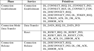
3.2 Connection-mode Services
The connection-mode services enable a DLS user to establish a data link connection, transfer data over that connection, reset the link, and release the connection when the conversation has terminated.
3.2.1 Connection Establishment Service
The connection establishment service establishes a data link connection between a local DLS user and a remote DLS user for the purpose of sending data. Only one data link connection is allowed on each stream.
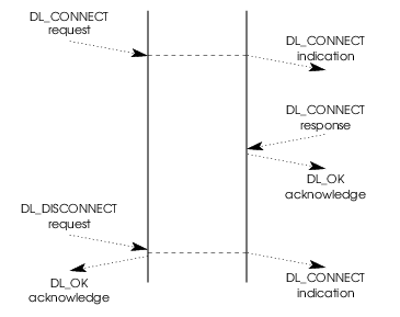
3.2.1.1 Normal Connection Establishment
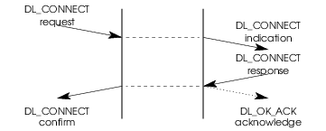
In the connection establishment model, the calling DLS user initiates connection
establishment, while the called DLS user waits for incoming requests.
DL_CONNECT_REQ requests that the DLS provider establish a connection.
DL_CONNECT_IND informs the called DLS user of the request, which may be
accepted using DL_CONNECT_RES. DL_CONNECT_CON informs the calling
DLS user that the connection has been established.
The normal sequence of messages is illustrated in the following figure.
Once the connection is established, the DLS users may exchange user data using
DL_DATA_REQ and DL_DATA_IND.
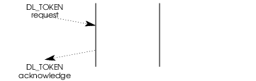
The DLS user may accept an incoming connect request on either the stream where
the connect indication arrived or an alternate, responding stream. The
responding stream is indicated by a token in the DL_CONNECT_RES. This
token is a value associated with the responding stream, and is obtained by
issuing a DL_TOKEN_REQ on that stream. The DLS provider responds to this
request by generating a token for the stream and returning it to the DLS user in
a DL_TOKEN_ACK. The normal sequence of messages for obtaining a token is
illustrated in the following figure.
In the typical connection establishment scenario, the called DLS user processes one connect indication at a time, accepting the connection on another stream. Once the user responds to the current connect indication, the next connect indication (if any) can be processed. DLPI also enables the called DLS user to multi-thread incoming connect indications. The user can receive multiple connect indications before responding to any of them. This enables the DLS user to establish priority schemes on incoming connect requests.
3.2.1.2 Connection Establishment Rejections
In certain situations, the connection establishment request cannot be completed.
The following paragraphs describe the occasions under which
DL_DISCONNECT_REQ
and DL_DISCONNECT_IND
primitives will flow during connection establishment, causing the connect
request to be aborted.
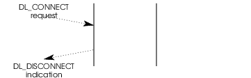
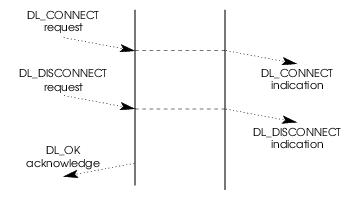
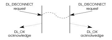
The following figure illustrates the situation where the called DLS user chooses
to reject the connect request by issuing DL_DISCONNECT_REQ instead of
The following figure illustrates the situation where the DLS provider rejects a
connect request for lack of resources or other reason. The DLS provider sends
DL_DISCONNECT_IND in response to
DL_CONNECT_REQ.
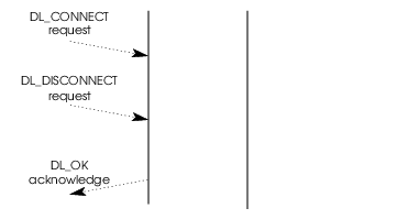
The following figures illustrate the situation where the calling DLS user
chooses to abort a previous connection attempt. The DLS user issues
DL_DISCONNECT_REQ at some point following a DL_CONNECT_REQ. The
resulting sequence of primitives depends on the relative timing of the
primitives involved, as defined in the following time sequence diagrams.
3.2.2 Data Transfer Service
The connection-mode data transfer service provides for the exchange of user data in either direction or in both directions simultaneously between DLS users. Data is transmitted in logical groups called data link service data units (DLSDUs). The DLS provider preserves both the sequence and boundaries of DLSDUs as they are transmitted.
Normal data transfer is neither acknowledged nor confirmed. It is up to the DLS users, if they so choose, to implement a confirmation protocol.
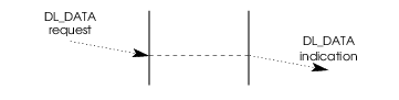
Each DL_DATA_REQ primitive conveys a DLSDU from the local DLS
user to the DLS provider. Similarly, each DL_DATA_IND primitive conveys
a DLSDU from the DLS provider to the remote DLS user. The normal flow
of messages is illustrated in the figure below.
3.2.3 Connection Release Service
The connection release service provides for the DLS users or the DLS provider to initiate the connection release. Connection release is an abortive operation, and any data in transit (has not been delivered to the DLS user) may be discarded.
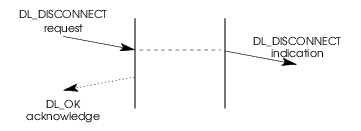
DL_DISCONNECT_REQ requests that a connection be released.
DL_DISCONNECT_IND informs the DLS user that a connection has been
released. Normally, one DLS user requests disconnection and the DLS provider
issues an indication of the ensuing release to the other DLS user, as
illustrated by the message flow in the following figure.
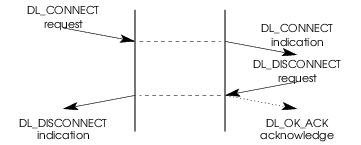
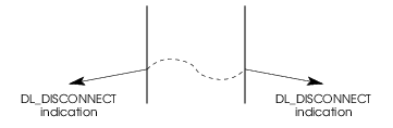
The next figure illustrates that when two DLS users independently invoke the
connection release service, neither receives a DL_DISCONNECT_IND.
The next figure illustrates that when the DLS provider initiates the connection
release service, each DLS user receives a DL_DISCONNECT_IND.
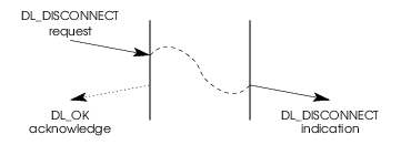
The next figure illustrates that when the DLS provider and the local DLS user
simultaneously invoke the connection release service, the remote DLS user
receives a DL_DISCONNECT_IND.
3.2.4 Reset Service
The reset service may be used by the DLS user to resynchronize the use of a data link connection, or by the DLS provider to report detected loss of data unrecoverable within the data link service.
Invocation of the reset service will unblock the flow of DLSDUs if the data link connection is congested; DLSDUs may be discarded by the DLS provider. The DLS user or users that did not invoke the reset will be notified that a reset has occurred. A reset may require a recovery procedure to be performed by the DLS users.
The interaction between each DLS user and the DLS provider will be one of the following:
- a
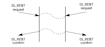
DL_RESET_REQfrom the DLS user, followed by aDL_RESET_CONfrom the DLS provider; - a
DL_RESET_INDfrom the DLS provider, followed by aDL_RESET_RESfrom the DLS user.
The DL_RESET_REQ
acts as a synchronization mark in the stream of DLSDUs that are transmitted by
the issuing DLS user; the
DL_RESET_IND
acts as a synchronization mark in the stream of DLSDUs that are received by the
peer DLS user. Similarly, the
DL_RESET_RES
acts as a synchronization mark in the stream of DLSDUs that are transmitted by
the responding DLS user; the
DL_RESET_CON
acts as a synchronization mark in the stream of DLSDUs that are received by the
DLS user which originally issued the reset.
The resynchronizing properties of the reset service are that:
- No DLSDU transmitted by the DLS user before the synchronization mark in that transmitted stream will be delivered to the other DLS user after the synchronization mark in that received stream.
- The DLS provider will discard all DLSDUs submitted before the issuing of
the
DL_RESET_REQthat have not been delivered to the peer DLS user when the DLS provider issues theDL_RESET_IND. - The DLS provider will discard all DLSDUs submitted before the issuing of
the
DL_RESET_RESthat have not been delivered to the initiator of theDL_RESET_REQwhen the DLS provider issues theDL_RESET_CON. - No DLSDU transmitted by a DLS user after the synchronization mark in that transmitted stream will be delivered to the other DLS user before the synchronization mark in that received stream.
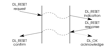
The complete message flow depends on the origin of the reset, which may be the DLS provider or either DLS user. The following figure illustrates the message flow for a reset invoked by one DLS user.

The following figure illustrates the message flow for a reset invoked by both DLS users simultaneously.
The following figure illustrates the message flow for a reset invoked by the DLS provider.
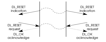
The following figure illustrates the message flow for a reset invoked simultaneously by one DLS user and the DLS provider.
3.3 Connectionless-mode Services
The connectionless-mode services enable a DLS user to transfer units of data to peer DLS users without incurring the overhead of establishing and releasing a connection. The connectionless service does not, however, guarantee reliable delivery of data units between peer DLS users (e.g. lack of flow control may cause buffer resource shortages that result in data being discarded).
Once a stream has been initialized via the local management services, it may be used to send and receive connectionless data units.
3.3.1 Connectionless Data Transfer Service
The connectionless data transfer service provides for the exchange of user data (DLSDUs) in either direction or in both directions simultaneously without having to establish a data link connection. Data transfer is neither acknowledged nor confirmed, and there is no end-to-end flow control provided. As such, the connectionless data transfer service cannot guarantee reliable delivery of data. However, a specific DLS provider can provide assurance that messages will not be lost, duplicated, or reordered.
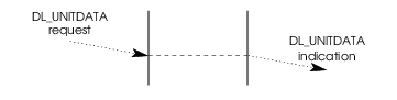
DL_UNITDATA_REQ conveys one DLSDU to the DLS provider.
DL_UNITDATA_IND conveys one DLSDU to the DLS user. The normal
flow of messages is illustrated
in the figure below.
3.3.2 QOS Management Service
The QoS (Quality of Service) management service enables a DLS user to specify
the quality of service it can expect for each invocation of the connectionless
data transfer service. The DL_UDQOS_REQ directs the DLS provider to set
the QoS parameters to the specified values. The
normal flow of messages is illustrated in the figure below.

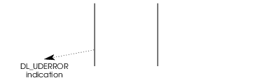
3.3.3 Error Reporting Service
The connectionless-mode error reporting service may be used to notify a DLS user that a previously sent data unit either produced an error or could not be delivered. This service does not, however, guarantee that an error indication will be issued for every undeliverable data unit.
3.3.4 XID and TEST Service
The XID and TEST service enables the DLS User to issue an XID or TEST request to the DLS Provider. On receiving a response for the XID or TEST frame transmitted to the peer DLS Provider, the DLS Provider sends up an XID or TEST confirmation primitive to the DLS User. On receiving an XID or TEST frame from the peer DLS Provider, the local DLS Provider sends up an XID or TEST indication respectively to the DLS User. The DLS User must respond with an XID or TEST response primitive.
If the DLS User requested automatic handling of the XID or TEST response, at bind time, the DLS Provider will send up an error acknowledgment on receiving an XID or TEST request. Also, no indications will be generated to the DLS User on receiving XID or TEST frames from the remote side.
The normal flow of messages is illustrated in the figure below.
3.4 Acknowledged Connectionless-mode Services
The acknowledged connectionless-mode services are designed for general use for the reliable transfer of informations between peer DLS Users. These services are intended for applications that require acknowledgment of cross-LAN data unit transfer, but wish to avoid the complexity that is viewed as being associated with the connection-mode services. Although the exchange service is connectionless, in sequence delivery is guaranteed for data sent by the initiating station.
3.4.1 Acknowledged Connectionless-mode Data Transfer Services
The acknowledged connectionless-mode data transfer services provide the means by which the DLS User scan exchange DLSDUs which are acknowledged at the LLC sublayer, without the establishment of a Data Link connection. The services provide a means by which a local DLS User can send a data unit to the peer DLS User, request a previously prepared data unit, or exchange data units with the peer DLS User.
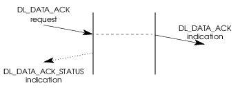
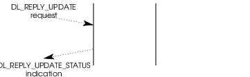
The next figure illustrates the acknowledged connectionless-mode data unit exchange service.
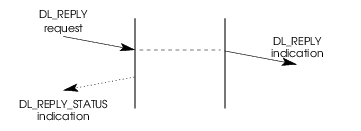
The next figure illustrates the Reply Data Unit Preparation service.
3.4.2 QOS Management Service
The Quality of Service (QoS) management service enables a DLS User to
specify the quality of service it can expect for each invocation of the
acknowledged connectionless data transfer service. The DL_UDQOS_REQ
directs the DLS provider to set the QoS parameters to the specified
values. The normal flow of messages is illustrated in Connectionless-mode Services.
3.4.3 Error Reporting Service
The acknowledged connectionless mode error reporting service is the same as the unacknowledged connectionless-mode error reporting service. For the message flow, refer to Error Reporting Service (1).
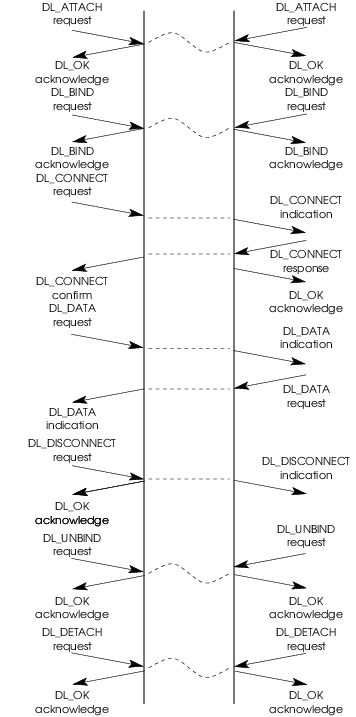
3.5 An Example
To bring it all together, the following example illustrates the primitives that flow during a complete, connection-mode sequence between stream open and stream close.
4 DLPI Primitives
The kernel-level interface to the data link layer defines a STREAMS-based message interface between the provider of the data link service (DLS provider) and the consumer of the data link service (DLS user). STREAMS provides the mechanism in which DLPI primitives may be passed between the DLS user and DLS provider.
Before DLPI primitives can be passed between the DLS user and the DLS provider, the DLS user must establish a stream to the DLS provider using open(2s). The DLS provider must therefore be configured as a STREAMS driver. When interactions between the DLS user and DLS provider have completed, the stream may be closed.
The STREAMS messages used to transport data link service primitives across the interface have one of the following formats:
- One
M_PROTOmessage block followed by zero or moreM_DATAblocks. TheM_PROTOmessage block contains the data link layer service primitive type and all relevant parameters associated with the primitive. TheM_DATAblock(s) contain any DLS user data that might be associated with the service primitive. - One
M_PCPROTOmessage block containing the data link layer service primitive type and all relevant parameters associated with the service primitive. - One or more
M_DATAmessage blocks conveying user data.
The information contained in the M_PROTO or M_PCPROTO message blocks
must begin on a byte boundary that is appropriate for structure alignment (e.g.
word-aligned on the AT&T 3B2 Computer). STREAMS will allocate buffers
that begin on such a boundary. However, these message blocks may contain
information whose representation is described by a length and an offset within
the block. An example is the DLSAP address (dl_addr_length and
dl_addr_offset) in the DL_BIND_ACK primitive. The offset of such
information within the message block is not guaranteed to be properly aligned
for casting the appropriate data type (such as an int or a structure).
Allowable Sequence of DLPI Primitives, defines the sequence in which DLPI primitives can be passed between DLS user and DLS provider, and Precedence of DLPI Primitives, summarizes the precedence rules associated with each primitive for ordering the primitives on the DLS provider and DLS user queues.
The following sections describe the format of the primitives that support the services described in the previous section. The primitives are grouped into four general categories for presentation:
- Local Management Service Primitives
- Connection-mode Service Primitives
- Connectionless-mode Service Primitives
- Acknowledged Connectionless-mode Service Primitives
4.1 Local Management Service Primitives
This section describes the local management service primitives that are common to the connection, connectionless and acknowledged connectionless service modes. These primitives support the Information Reporting, Attach, Bind, enabling/disabling of multicast addresses and turning on/off the promiscuous mode. Once a stream has been opened by a DLS user, these primitives initialize the stream, preparing it for use.
4.1.1 PPA Initialization / De-initialization
The PPA associated with each stream must be initialized before the DLS
provider can transfer data over the medium. The initialization and
de-initialization of the PPA is a network management issue, but
DLPI
must address the issue because of the impact such actions will have on a DLS
user. More specifically, DLPI requires the DLS provider to initialize the
PPA associated with a stream at some point before it completes the
processing of the DL_BIND_REQ. Guidelines for initialization and
de-initialization of a PPA by a DLS provider are presented here.
A DLS provider may initialize a PPA using the following methods:
- pre-initialized by some network management mechanism before the
DL_BIND_REQis received; or - automatic initialization on receipt of a
DL_BIND_REQorDL_ATTACH_REQ.
A specific DLS provider may support either of these methods, or possibly some
combination of the two, but the method implemented has no impact on the DLS
user. From the DLS user’s viewpoint, the PPA is guaranteed to be
initialized on receipt of a DL_BIND_ACK. For automatic initialization,
this implies that the DL_BIND_ACK may not be issued until the
initialization has completed.
If pre-initialization has not been performed and/or automatic initialization
fails, the DLS provider will fail the DL_BIND_REQ. Two errors,
[DL_INITFAILED] and [DL_NOTINIT], may be returned in the
DL_ERROR_ACK response to a DL_BIND_REQ if PPA
initialization fails. [DL_INITFAILED] is returned when a DLS provider
supports automatic PPA initialization, but the initialization attempt
failed. [DL_NOTINIT] is returned when the DLS provider requires
pre-initialization, but the PPA is not initialized before the
DL_BIND_REQ is received.
A DLS provider may handle PPA de-initialization using the following methods:
- automatic de-initialization upon receipt of the final
DL_DETACH_REQ(for style 2 providers) orDL_UNBIND_REQ(for style 1 providers), or upon closing of the last stream associated with the PPA; - automatic de-initialization after expiration of a timer following the last
DL_DETACH_REQ,DL_UNBIND_REQ, or close as appropriate; or - no automatic de-initialization; administrative intervention is required to de-initialize the PPA at some point after it is no longer being accessed.
A specific DLS provider may support any of these methods, or possibly some combination of them, but the method implemented has no impact on the DLS user. From the DLS user’s viewpoint, the PPA is guaranteed to be initialized and available for transmission until it closes or unbinds the stream associated with the PPA.
DLS provider-specific addendum documentation should describe the method chosen for PPA initialization and de-initialization.
4.1.2 Message DL_INFO_REQ (dl_info_req_t)
Requests information of the DLS provider about the DLPI stream. This information includes a set of provider-specific parameters, as well as the current state of the interface.
Message Format
The message consists of one M_PCPROTO message block, which contains the
following structure.
Parameters
- dl_primitive
conveys
DL_INFO_REQ.
State
The message is valid in any state in which a local acknowledgment is not pending, as described in Allowable Sequence of DLPI Primitives.
New State
The resulting state is unchanged.
Response
The DLS provider responds to the information request with a
DL_INFO_ACK.
4.1.3 Message DL_INFO_ACK (dl_info_ack_t)
This message is sent in response to
DL_INFO_REQ;
it conveys information about
the DLPI stream to the DLS user.
Message Format
The message consists of one M_PCPROTO message block, which contains the
following structure.
typedef struct {
        ulong dl_primitive;
        ulong dl_max_sdu;
        ulong dl_min_sdu;
        ulong dl_addr_length;
        ulong dl_mac_type;
        ulong dl_reserved;
        ulong dl_current_state;
        long dl_sap_length;
        ulong dl_service_mode;
        ulong dl_qos_length;
        ulong dl_qos_offset;
        ulong dl_qos_range_length;
        ulong dl_qos_range_offset;
        ulong dl_provider_style;
        ulong dl_addr_offset;
        ulong dl_version;
        ulong dl_brdcst_addr_length;
        ulong dl_brdcst_addr_offset;
        ulong dl_growth;
} dl_info_ack_t;
Parameters
- dl_primitive
conveys
DL_INFO_ACK.- dl_max_sdu
conveys the maximum number of bytes that may be transmitted in a DLSDU. This value must be a positive integer that is greater than or equal to the value of dl_min_sdu.
- dl_min_sdu
conveys the minimum number of bytes that may be transmitted in a DLSDU. The value is never less than one.
- dl_addr_length
conveys the length, in bytes, of the provider’s DLSAP address. In the case of a hierarchical subsequent bind, the length returned is the total length i.e. Physical address + SAP + subsequent address length.
- dl_mac_type
conveys the type of medium supported by this DLPI stream. Possible values include:
DL_CSMACDThe medium is Carrier Sense Multiple Access with Collision Detection (ISO8802/3).
DL_TPBThe medium is Token-Passing Bus (ISO 8802/4).
DL_TPRThe medium is Token-Passing Ring (ISO 8802/5).
DL_METROThe medium is Metro Net (ISO 8802/6).
DL_ETHERThe medium is Ethernet Bus.
DL_HDLCThe medium is a bit synchronous communication line.
DL_CHARThe medium is a character synchronous communication line (e.g. BISYNC).
DL_CTCAThe medium is a channel-to-channel adapter.
DL_FDDIThe medium is a Fiber Distributed Data Interface.
DL_OTHERAny other medium not listed above.
- dl_reserved
is a reserved field whose value must be set to zero.
- dl_current_state
conveys the state of the DLPI interface for the stream when the DLS provider issued this acknowledgment. See Allowable Sequence of DLPI Primitives, for a list of DLPI states and an explanation of each.
- dl_sap_length
indicates the current length of the SAP component of the DLSAP address. It may have a negative, zero or positive value. A positive value indicates the ordering of the SAP and PHYSICAL component within the DLSAP address as SAP component followed by PHYSICAL component. A negative value indicates PHYSICAL followed by the SAP. A zero value indicates that no SAP has yet been bound. The absolute value of the dl_sap_length provides the length of the SAP component within the DLSAP address.
- dl_service_mode
if returned before the
DL_BIND_REQis processed, this conveys which service modes (connection-mode, connectionless-mode or acknowledged connectionless-mode, or any combination of these modes) the DLS provider can support. It contains a bit-mask specifying one or more than one of the following values:DL_CODLSconnection-oriented data link service;
DL_CLDLS-
connectionless data link service;
DL_ACLDLS-
acknowledged connectionless data link service;
Once a specific service mode has been bound to the stream, this field returns that specific service mode.
- dl_qos_length
conveys the length, in bytes, of the negotiated/selected values of the quality of service (QoS) parameters. Quality of Data Link Service, describes quality of service and its associated parameters completely. For connection-mode service, the returned values are those agreed during negotiation. For connectionless-mode service, the values are those currently selected by the DLS user. If quality of service has not yet been negotiated, default values will be returned; these values correspond to those that will be applied by the DLS provider on a connect request in connection-mode service, or those that will be applied to each data unit transmission in connectionless-mode service. If the DLS provider supports both connection-mode and connectionless-mode services but the DLS user has not yet bound a specific service mode, the DLS provider may return either connection-mode or connectionless-mode QoS parameter values.
The QoS values are conveyed in the structures defined in QOS Data Structures. For any parameter the DLS provider does not support or cannot determine, the corresponding entry will be set to
DL_UNKNOWN. If the DLS provider does not support any QoS parameters, this length field will be set to zero.- dl_qos_offset
conveys the offset from the beginning of the
M_PCPROTOblock where the current quality of service parameters begin.- dl_qos_range_length
-
conveys the length, in bytes, of the available range of QoS parameter values supported by the DLS provider. For connection-mode service, this is the range available to the calling DLS user in a connect request. For connectionless-mode, this is the range available for each data unit transmission. If the DLS provider supports both connection-mode and connectionless-mode services but the DLS user has not yet bound a specific service mode, the DLS provider may return either connection-mode or connectionless-mode QoS parameter values. The range of available QoS values is conveyed in the structures defined in QOS Data Structures. For any parameter the DLS provider does not support or cannot determine, the corresponding entry will be set to
DL_UNKNOWN. If the DLS provider does not support any QoS parameters, this length field will be set to zero. - dl_qos_range_offset
conveys the offset from the beginning of the
M_PCPROTOblock where the available range of quality of service parameters begins.- dl_provider_style
conveys the style of DLS provider associated with the DLPI stream (see Physical Attachment Identification). The following provider classes are defined:
DL_STYLE1The PPA is implicitly attached to the DLPI stream by opening the appropriate major/minor device number.
DL_STYLE2The DLS user must explicitly attach a PPA to the DLPI stream using
DL_ATTACH_REQ.
DLS users implemented in a protocol-independent manner must access this parameter to determine whether the DLS attach service must be invoked explicitly.
- dl_addr_offset
conveys the offset of the address that is bound to the associated stream. If the DLS user issues a
DL_INFO_REQprior to binding a DLSAP, the value of dl_addr_len will be 0 and consequently indicate that there has been no address bound.- dl_version
indicates the current version of the DLPI that’s supported.
- dl_brdcst_addr_length
indicates the length of the physical broadcast address.
- dl_brdcst_addr_offset
indicates the offset of the physical broadcast address from the beginning of the
M_PCPROTOblock.- dl_growth
conveys a growth field for future use. The value of this field will be zero.
State
The message is valid in any state in response to a
DL_INFO_REQ.
New State
The resulting state is unchanged.
4.1.4 Message DL_ATTACH_REQ (dl_attach_req_t)
Requests the DLS provider associate a physical point of attachment
(PPA) with a stream. DL_ATTACH_REQ is needed for style 2 DLS
providers to identify the physical medium over which communication will
transpire. The request may not be issued to a style 1 DLS provider; doing so
may cause errors.
The DLS provider may initialize the physical line on receipt of this primitive
or the DL_BIND_REQ. Otherwise, the line must be initialized through some
management mechanism before this request is issued by the DLS user. Either way,
the physical link must be initialized and ready for use on successful completion
of the DL_BIND_REQ.
Message Format
The message consists of one M_PROTO message block, which contains the
following structure.
Parameters
- dl_primitive
conveys
DL_ATTACH_REQ.- dl_ppa
conveys the identifier of the physical point of attachment to be associated with the stream. The format of the identifier is provider-specific, and it must contain sufficient information to distinguish the desired PPA from all possible PPAs on a system.
At a minimum, this must include identification of the physical medium over which communication will transpire. For media that multiplex multiple channels over a single physical medium, this identifier should also specify a specific channel to be used for communication(where each channel on a physical medium is associated with a separate PPA).
Because of the provider-specific nature of this value, DLS user software that is to be protocol independent should avoid hard-coding the PPA identifier. The DLS user should retrieve the necessary PPA identifier from some other entity (such as a management entity) and insert it without inspection into the
DL_ATTACH_REQ.
State
The message is valid in state
DL_UNATTACHED.
New State
The resulting state is
DL_ATTACH_PENDING.
Response
If the attach request is successful,
DL_OK_ACK
is sent to the DLS user resulting
in state
DL_UNBOUND.
If the request fails, message
DL_ERROR_ACK
is returned and the resulting state is unchanged.
Reasons for Failure
[DL_BADPPA]The specified PPA is invalid.
[DL_ACCESS]The DLS user did not have proper permission to use the requested PPA.
[DL_OUTSTATE]The primitive was issued from an invalid state.
[DL_SYSERR]A system error has occurred and the UNIX system error is indicated in the
DL_ERROR_ACK.
4.1.5 Message DL_DETACH_REQ (dl_detach_req_t)
For style 2 DLS providers, this requests the DLS provider detach a physical point of attachment (PPA) from a stream. The request may not be issued to a style 1 DLS provider; doing so may cause errors.
Message Format
The message consists of one M_PROTO message block, which contains the
following structure.
Parameters
- dl_primitive
conveys
DL_DETACH_REQ.
State
The message is valid in state
DL_UNBOUND.
New State
The resulting state is
DL_DETACH_PENDING.
Response
If the detach request is successful,
DL_OK_ACK
is sent to the DLS user resulting in state
DL_UNATTACHED.
If the request fails, message
DL_ERROR_ACK
is returned and the resulting state is unchanged.
Reasons for Failure
[DL_OUTSTATE]The primitive was issued from an invalid state.
[DL_SYSERR]A system error has occurred and the UNIX system error is indicated in the
DL_ERROR_ACK.
4.1.6 Message DL_BIND_REQ (dl_bind_req_t)
Requests the DLS provider bind a DLSAP to the stream. The DLS user must identify the address of the DLSAP to be bound to the stream. For connection-mode service, the DLS user also indicates whether it will accept incoming connection requests on the stream. Finally, the request directs the DLS provider to activate the stream associated with the DLSAP.
A stream is viewed as active when the DLS provider may transmit and receive
protocol data units destined to or originating from the stream. The
PPA associated with each stream must be initialized upon completion of
the processing of the DL_BIND_REQ (see PPA Initialization / De-initialization). More specifically, the DLS user is ensured that the
PPA is initialized when the DL_BIND_ACK is received. If the
PPA cannot be initialized, the DL_BIND_REQ will fail.
A stream may be bound as a "connection management" stream, such that it will receive all connect requests that arrive through a given PPA (see The Connection Management Stream). In this case, the dl_sap will be ignored.
Message Format
The message consists of one M_PROTO message block, which contains the
following structure.
typedef struct {
        ulong dl_primitive;
        ulong dl_sap;
        ulong dl_max_conind;
        ushort dl_service_mode;
        ushort dl_conn_mgmt;
        ulong dl_xidtest_flg;
} dl_bind_req_t;
Parameters
- dl_primitive
conveys
DL_BIND_REQ.- dl_sap
conveys sufficient information to identify the DLSAP that will be bound to the DLPI stream (see DLPI Addressing, for a description of DLSAP addresses). The format of this information is specific to a given DLS provider, and may contain the full DLSAP address or some portion of that address sufficient to uniquely identify the DLSAP in question. The full address of the bound DLSAP will be returned in the
DL_BIND_ACK.The following rules are used by the DLS provider when binding a DLSAP address.
- The DLS provider must define and manage its DLSAP address space.
- DLPI allows the same DLSAP to be bound to multiple streams, but a given DLS provider may need to restrict its address space to allow one stream per DLSAP.
- The DLS provider may not be able to bind the specified DLSAP
address for the following reasons:
- the DLS provider may statically associate a specific DLSAP with each stream; or
- the DLS provider may only support one stream per DLSAP and the DLS user attempted to bind a DLSAP that was already bound to another stream.
In case (1), the value of dl_sap is ignored by the DLS provider and the
DL_BIND_ACKreturns the DLSAP address that is already associated with the stream. In case (2), if the DLS provider cannot bind the given DLSAP to the stream, it may attempt to choose an alternate DLSAP and return that on theDL_BIND_ACK. If an alternate DLSAP cannot be chosen, the DLS provider will return aDL_ERROR_ACKand set dl_errno to[DL_NOADDR].
Because of the provider-specific nature of the DLSAP address, DLS user software that is to be protocol independent should avoid hard-coding this value. The DLS user should retrieve the necessary DLSAP address from some other entity (such as a management entity or higher layer protocol entity) and insert it without inspection into the
DL_BIND_REQ.- dl_max_conind
conveys the maximum number of outstanding
DL_CONNECT_INDmessages allowed on the DLPI stream. If the value is zero, the stream cannot accept anyDL_CONNECT_INDmessages. If greater than zero, the DLS user will acceptDL_CONNECT_INDmessages up to the given value before having to respond with aDL_CONNECT_RESor aDL_DISCONNECT_REQ(see Multi-threaded Connection Establishment, for details on how this value is used to support multi-threaded connect processing). The DLS provider may not be able to support the value supplied in dl_max_conind, as specified by the following rules.- If the provider cannot support the specified number of outstanding connect indications, it should set the value down to a number it can support.
- Only one stream that is bound to the indicated DLSAP may have an
allowed number of maximum outstanding connect indications greater than zero. If
a
DL_BIND_REQspecifies a value greater than zero, but another stream has already bound itself to the DLSAP with a value greater than zero, the DLS provider will fail the request, setting dl_errno to[DL_BOUND]on theDL_ERROR_ACK. - If a stream with dl_max_conind greater than zero is used to accept a connection, the stream will be found busy during the duration of the connection, and no other streams may be bound to the same DLSAP with a value of dl_max_conind greater than zero. This restriction prevents more than one stream bound to the same DLSAP from receiving connect indications and accepting connections. Accepting a connection on such a stream is only allowed if there is just a single outstanding connect indication being processed.
- A DLS user should always be able to request a dl_max_conind value of zero, since this indicates to the DLS provider that the stream will only be used to originate connect requests.
- A stream with a negotiated value of dl_max_conind that is greater than zero may not originate connect requests.
This field is ignored in connectionless-mode service.
- dl_service_mode
conveys the desired mode of service for this stream, and may contain one of the following:
DL_CODLSconnection-oriented data link service;
DL_CLDLS-
connectionless data link service.
DL_ACLDLS-
acknowledged connectionless data link service.
If the DLS provider does not support the requested service mode, a
DL_ERROR_ACKwill be generated, specifying[DL_UNSUPPORTED].- dl_conn_mgmt
-
if non-zero, indicates that the stream is the "connection management" stream for the PPA to which the stream is attached. When an incoming connect request arrives, the DLS provider will first look for a stream bound with dl_max_conind greater than zero that is associated with the destination DLSAP. If such a stream is found, the connect indication will be issued on that stream. Otherwise, the DLS provider will issue the connect indication on the "connection management" stream for that PPA, if one exists. Only one "connection management" stream is allowed per PPA, so an attempt to bind a second "connection management" stream on a PPA will fail with the DLPI error set to
[DL_BOUND]. When dl_conn_mgmt is non-zero, the value of dl_sap will be ignored. In connectionless-mode service, dl_conn_mgmt is ignored by the DLS provider. - dl_xidtest_flg
indicates to the DLS Provider that XID and/or TEST responses for this stream are to be automatically generated by the DLS Provider. The DLS Provider will not generate
DL_XID_INDand/orDL_TEST_IND, and will error aDL_XID_REQand/orDL_TEST_REQ. If the DLS Provider does not support automatic handling of XID and/or TEST responses, aDL_ERROR_ACKwill be generated, specifying[DL_NOAUTO],[DL_NOXIDAUTO]or[DL_NOTESTAUTO]. If the Provider receives an XID or TEST request from the DLS User, aDL_ERROR_ACKwill be generated specifying[DL_XIDAUTO]or[DL_TESTAUTO]respectively.The dl_xidtest_flg contains a bit-mask specifying zero or more of the following values:
DL_AUTO_XIDAutomatically respond to XID commands.
DL_AUTO_TESTAutomatically respond to TEST commands.
State
The message is valid in state
DL_UNBOUND.
New State
The resulting state is
DL_BIND_PENDING.
Response
If the bind request is successful,
DL_BIND_ACK
is sent to the DLS user resulting in state
DL_IDLE.
If the request fails, message
DL_ERROR_ACK
is returned and the resulting state is unchanged.
Reasons for Failure
[DL_BADADDR]The DLSAP address information was invalid or was in an incorrect format.
[DL_INITFAILED]Automatic initialization of the PPA failed.
[DL_NOTINIT]The PPA had not been initialized prior to this request.
[DL_ACCESS]The DLS user did not have proper permission to use the requested DLSAP address.
[DL_BOUND]The DLS user attempted to bind a second stream to a DLSAP with dl_max_conindgreater than zero, or the DLS user attempted to bind a second "connection management" stream to a PPA.
[DL_OUTSTATE]The primitive was issued from an invalid state.
[DL_NOADDR]The DLS provider could not allocate a DLSAP address for this stream.
[DL_UNSUPPORTED]The DLS provider does not support requested service mode on this stream.
[DL_SYSERR]A system error has occurred and the UNIX system error is indicated in the
DL_ERROR_ACK.[DL_NOAUTO]Automatic handling of XID and TEST responses not supported.
[DL_NOXIDAUTO]Automatic handling of XID response not supported.
[DL_NOTESTAUTO]Automatic handling of TEST response not supported.
4.1.7 Message DL_BIND_ACK (dl_bind_ack_t)
Reports the successful bind of a DLSAP to a stream, and returns the
bound DLSAP address to the DLS user. This primitive is generated in
response to a DL_BIND_REQ.
Message Format
The message consists of one M_PCPROTO message block, which contains the
following structure.
typedef struct {
        ulong dl_primitive;
        ulong dl_sap;
        ulong dl_addr_length;
        ulong dl_addr_offset;
        ulong dl_max_conind;
        ulong dl_xidtest_flg;
} dl_bind_ack_t;
Parameters
- dl_primitive
conveys
DL_BIND_ACK.- dl_sap
conveys the DLSAP address information associated with the bound DLSAP. It corresponds to the dl_sap field of the associated
DL_BIND_REQ, which contains either part or all of the DLSAP address. For that portion of the DLSAP address conveyed in theDL_BIND_REQ, this field contains the corresponding portion of the address for the DLSAP that was actually bound.- dl_addr_length
conveys the length of the complete DLSAP address that was bound to the DLPI stream (see DLPI Addressing, for a description of DLSAP addresses). The bound DLSAP is chosen according to the guidelines presented under the description of
DL_BIND_REQ.- dl_addr_offset
conveys the offset from the beginning of the
M_PCPROTOblock where the DLSAP address begins.- dl_max_conind
conveys the allowed, maximum number of outstanding
DL_CONNECT_INDmessages to be supported on the DLPI stream. If the value is zero, the stream cannot accept anyDL_CONNECT_INDmessages. If greater than zero, the DLS user will acceptDL_CONNECT_INDmessages up to the given value before having to respond with aDL_CONNECT_RESor aDL_DISCONNECT_REQ. The rules for negotiating this value are presented under the description ofDL_BIND_REQ.- dl_xidtest_flg
conveys the XID and TEST responses supported by the provider.
DL_AUTO_XIDXID response handled automatically.
DL_AUTO_TESTTEST response handled automatically.
If no value is specified in dl_xidtest_flg, it indicates that automatic handling of XID and TEST responses is not supported by the Provider.
State
The message is valid in state
DL_BIND_PENDING.
New State
The resulting state is
DL_IDLE.
4.1.8 Message DL_UNBIND_REQ (dl_unbind_req_t)
Requests the DLS provider to unbind the DLSAP that had been bound by a
previous DL_BIND_REQ from this stream. If one or more DLSAPs were bound
to the stream using a DL_SUBS_BIND_REQ, and have not been unbound using a
DL_SUBS_UNBIND_REQ, the DL_UNBIND_REQ will unbind all the
subsequent DLSAPs for that stream along with the DLSAP bound using the
previous DL_BIND_REQ.
At the successful completion of the request, the DLS user may issue a new
DL_BIND_REQ for a potentially new DLSAP.
Message Format
The message consists of one M_PROTO message block, which contains the
following structure.
Parameters
- dl_primitive
conveys
DL_UNBIND_REQ.
State
The message is valid in state
DL_IDLE.
New State
The resulting state is
DL_UNBIND_PENDING.
Response
If the unbind request is successful,
DL_OK_ACK
is sent to the DLS user resulting in state
DL_UNBOUND.
If the request fails, message
DL_ERROR_ACK
is returned and the resulting state is unchanged.
Reasons for Failure
[DL_OUTSTATE]The primitive was issued from an invalid state.
[DL_SYSERR]A system error has occurred and the UNIX system error is indicated in the
DL_ERROR_ACK.
4.1.9 Message DL_SUBS_BIND_REQ (dl_subs_bind_req_t)
Requests the DLS provider bind a subsequent DLSAP to the stream. The DLS user must identify the address of the subsequent DLSAP to be bound to the stream.
Message Format
The message consists of one M_PROTO message block, which contains the
following structure.
typedef struct {
        ulong dl_primitive;
        ulong dl_subs_sap_offset;
        ulong dl_subs_sap_length;
        ulong dl_subs_bind_class;
} dl_subs_bind_req_t;
Parameters
- dl_primitive
conveys
DL_SUBS_BIND_REQ.- dl_subs_sap_offset
conveys the offset of the DLSAP from the beginning of the
M_PROTOblock.- dl_subs_sap_length
conveys the length of the specified DLSAP.
- dl_subs_bind_class
Specifies either peer or hierarchical addressing
DL_PEER_BINDspecifies peer addressing. The DLSAP specified is used in lieu of the DLSAP bound in the BIND request.
DL_HIERARCHICAL_BINDspecifies hierarchical addressing. The DLSAP specified is used in addition to the DLSAP specified using the BIND request.
State
The message is valid in state
DL_IDLE.
New State
The resulting state is
DL_SUBS_BIND_PND.
Response
If the subsequent bind request is successful,
DL_SUBS_BIND_ACK
is sent to the DLS user resulting instate
DL_IDLE.
If the request fails, message
DL_ERROR_ACK
is returned and the resulting state is unchanged.
Reasons for Failure
[DL_BADADDR]The DLSAP address information was invalid or was in an incorrect format.
[DL_ACCESS]The DLS user did not have proper permission to use the requested DLSAP address.
[DL_OUTSTATE]The primitive was issued from an invalid state.
[DL_SYSERR]A System error has occurred and the UNIX system error is indicated in the
DL_ERROR_ACK.[DL_UNSUPPORTED]Requested addressing class not supported.
[DL_TOOMANY]Limit exceeded on the maximum number of DLSAPs per stream.
4.1.10 Message DL_SUBS_BIND_ACK (dl_subs_bind_ack_t)
Reports the successful bind of a subsequent DLSAP to a stream, and
returns the bound DLSAP address to the DLS user. This primitive is
generated in response to a DL_SUBS_BIND_REQ.
Message Format
The message consists of one M_PCPROTO message block, which contains the
following structure.
typedef struct {
        ulong dl_primitive;
        ulong dl_subs_sap_offset;
        ulong dl_subs_sap_length;
} dl_subs_bind_ack_t;
Parameters
- dl_primitive
conveys
DL_SUBS_BIND_ACK.- dl_subs_sap_offset
conveys the offset of the DLSAP from the beginning of the
M_PCPROTOblock.- dl_subs_sap_length
conveys the length of the specified DLSAP.
State
The message is valid in state
DL_SUBS_BIND_PND
New State
The resulting state is
DL_IDLE.
4.1.11 Message DL_SUBS_UNBIND_REQ (dl_subs_unbind_req_t)
Requests the DLS Provider to unbind the DLSAP that had been bound by a
previous DL_SUBS_BIND_REQ from this stream.
Message Format
The message consists of one M_PROTO message block, which contains the
following structure:
typedef struct {
        ulong dl_primitive;
        ulong dl_subs_sap_offset;
        ulong dl_subs_sap_length;
} dl_subs_unbind_req_t;
Parameters
- dl_primitive
conveys
DL_SUBS_UNBIND_REQ.- dl_subs_sap_offset
conveys the offset of the DLSAP from the beginning of the
M_PROTOblock.- dl_subs_sap_length
conveys the length of the specified DLSAP.
State
The message is valid in state
DL_IDLE.
New State
The resulting state is
DL_SUBS_UNBIND_PND.
Response
If the unbind request is successful, a
DL_OK_ACK
is sent to the DLS User. The resulting state is
DL_IDLE.
If the request fails, message
DL_ERROR_ACK
is returned and the resulting state is unchanged.
Reasons for failure
[DL_OUTSTATE]The primitive was issued from an invalid state
[DL_SYSERR]A system error has occurred and the UNIX system error is indicated in the
DL_ERROR_ACK.[DL_BADADDR]The DLSAP address information was invalid or was in an incorrect format.
4.1.12 Message DL_ENABMULTI_REQ (dl_enabmulti_req_t)
Requests the DLS Provider to enable specific multicast addresses on a per Stream basis. It is invalid for a DLS Provider to pass upstream messages that are destined for any address other than those explicitly enabled on that Stream by the DLS User.
Message Format
The message consists of one M_PROTO message block, which contains the following
structure:
typedef struct {
        ulong dl_primitive;
        ulong dl_addr_length;
        ulong dl_addr_offset;
} dl_enabmulti_req_t;
Parameters
- dl_primitive
conveys
DL_ENABMULTI_REQ- dl_addr_length
conveys the length of the multicast address
- dl_addr_offset
conveys the offset from the beginning of the
M_PROTOmessage block where the multicast address begins
State
This message is valid in any state in which a local acknowledgment is not
pending with the exception of
DL_UNATTACHED.
New State
The resulting state is unchanged.
Response
If the enable request is successful, a
DL_OK_ACK
is sent to the DLS user.
If the request fails, message
DL_ERROR_ACK
is returned and the resulting state is unchanged.
Reasons for failure
[DL_BADADDR]Address information was invalid or was in an incorrect format.
[DL_TOOMANY]Too many multicast address enable attempts. Limit exceeded.
[DL_OUTSTATE]The primitive was issued from an invalid state
[DL_NOTSUPPORTED]The primitive is known, but not supported by the DLS Provider.
4.1.13 Message DL_DISABMULTI_REQ (dl_disabmulti_req_t)
Requests the DLS Provider to disable specific multicast addresses on a per Stream basis.
Message Format
The message consists of one M_PROTO message block, which contains the following
structure:
typedef struct {
        ulong dl_primitive;
        ulong dl_addr_length;
        ulong dl_addr_offset;
} dl_disabmulti_req_t;
Parameters
- dl_primitive
conveys
DL_DISABMULTI_REQ- dl_addr_length
conveys the length of the physical address
- dl_addr_offset
conveys the offset from the beginning of the
M_PROTOmessage block where the multicast address begins
State
This message is valid in any state in which a local acknowledgment is not
pending with the exception of
DL_UNATTACHED.
New State
The resulting state is unchanged.
Response
If the disable request is successful, a
DL_OK_ACK
is sent to the DLS user.
If the request fails, message
DL_ERROR_ACK
is returned and the resulting state is unchanged.
Reasons for failure
[DL_BADADDR]Address information was invalid or in an incorrect format.
[DL_NOTENAB]Address specified is not enabled.
[DL_OUTSTATE]The primitive was issued from an invalid state.
[DL_NOTSUPPORTED]Primitive is known, but not supported by the DLS Provider.
4.1.14 Message DL_PROMISCON_REQ (dl_promiscon_req_t)
This primitive requests the DLS Provider to enable promiscuous mode on a per Stream basis, either at the physical level or at the SAP level.
The DL Provider will route all received messages on the media to the DLS User
until either a
DL_DETACH_REQ
or a
DL_PROMISCOFF_REQ
is received or the Stream is
closed.
Message Format
The message consists of one M_PROTO message block, which contains the following
structure.
Parameters
- dl_primitive
conveys
DL_PROMISCON_REQ- dl_level
indicates promiscuous mode at the physical or SAP level
DL_PROMISC_PHYSindicates promiscuous mode at the physical level
DL_PROMISC_SAPindicates promiscuous mode at the SAP level
DL_PROMISC_MULTIindicates promiscuous mode for all multicast addresses
State
The message is valid in any state when there is no pending acknowledgment.
New State
The resulting state is unchanged.
Response
If enabling of promiscuous mode is successful, a
DL_OK_ACK
is returned. Otherwise, a
DL_ERROR_ACK
is returned.
Reasons for Failure
[DL_OUTSTATE]The primitive was issued from an invalid state
[DL_SYSERR]A System error has occurred and the UNIX System error is indicated in the
DL_ERROR_ACK.[DL_NOTSUPPORTED]Primitive is known but not supported by the DLS Provider
[DL_UNSUPPORTED]Requested service is not supplied by the provider.
4.1.15 Message DL_PROMISCOFF_REQ (dl_promiscoff_req_t)
This primitive requests the DLS Provider to disable promiscuous mode on a per Stream basis, either at the physical level or at the SAP level.
Message Format
The message consists of one M_PROTO message block, which contains the following
structure.
Parameters
- dl_primitive
conveys
DL_PROMISCOFF_REQ- dl_level
indicates promiscuous mode at the physical or SAP level
DL_PROMISC_PHYSindicates promiscuous mode at the physical level
DL_PROMISC_SAPindicates promiscuous mode at the SAP level
DL_PROMISC_MULTIindicates promiscuous mode for all multicast addresses
State
The message is valid in any state in which the promiscuous mode is enabled and there is no pending acknowledgment.
New State
The resulting state is unchanged.
Response
If the promiscuous mode disabling is successful, a
DL_OK_ACK
is returned. Otherwise, a
DL_ERROR_ACK
is returned.
Reasons for Failure
[DL_OUTSTATE]The primitive was issued from an invalid state
[DL_SYSERR]A System error has occurred and the UNIX System error is indicated in the
DL_ERROR_ACK.[DL_NOTSUPPORTED]Primitive is known but not supported by the DLS Provider
[DL_NOTENAB]Mode not enabled.
4.1.16 Message DL_OK_ACK (dl_ok_ack_t)
Acknowledges to the DLS user that a previously issued request primitive was received successfully. It is only initiated for those primitives that require a positive acknowledgment.
Message Format
The message consists of one M_PCPROTO message block, which contains the
following structure.
Parameters
- dl_primitive
conveys
DL_OK_ACK.- dl_correct_primitive
identifies the successfully received primitive that is being acknowledged.
State
The message is valid in response to a
DL_ATTACH_REQ,
DL_DETACH_REQ,
DL_UNBIND_REQ,
DL_CONNECT_RES,
DL_RESET_RES,
DL_DISCONNECT_REQ,
DL_SUBS_UNBIND_REQ,
DL_PROMISCON_REQ,
DL_ENABMULTI_REQ,
DL_DISABMULTI_REQ or
DL_PROMISCOFF_REQ
from any of several states as defined in Allowable Sequence of DLPI Primitives.
New State
The resulting state depends on the current state and is defined fully in Allowable Sequence of DLPI Primitives.
4.1.17 Message DL_ERROR_ACK (dl_error_ack_t)
Informs the DLS user that a previously issued request or response was invalid. It conveys the identity of the primitive in error, a DLPI error code, and if appropriate, a UNIX system error code.
Whenever this primitive is generated, it indicates that the DLPI state is identical to what it was before the erroneous request or response.
Message Format
The message consists of one M_PCPROTO message block, which contains the
following structure.
typedef struct {
        ulong dl_primitive;
        ulong dl_error_primitive;
        ulong dl_errno;
        ulong dl_unix_errno;
} dl_error_ack_t;
Parameters
- dl_primitive
conveys
DL_ERROR_ACK.- dl_error_prim
identifies the primitive in error.
- dl_errno
conveys the DLPI error code associated with the failure. See the individual request or response for the error codes that are applicable. In addition to those errors:
- – DL_BADPRIM error is returned if an unrecognized primitive is issued by the DLS user.
- – DL_NOTSUPPORTED error is returned if an unsupported primitive is issued by the DLS user.
- dl_unix_errno
conveys the UNIX system error code associated with the failure. This value should be non-zero only when dl_errno is set to
[DL_SYSERR]. It is used to report UNIX system failures that prevent the processing of a given request or response.
State
The message is valid in every state where an acknowledgment or confirmation of a previous request or response is pending.
New State
The resulting state is that from which the acknowledged request or response was generated.
4.2 Connection-mode Service Primitives
This section describes the service primitives that support the connection-mode service of the data link layer. These primitives support the connection establishment, connection-mode data transfer, and connection release services described earlier.
4.2.1 Multi-threaded Connection Establishment
In the connection establishment model, the calling DLS user initiates a request for a connection, and the called DLS user receives each request and either accepts or rejects it. In the simplest form (single threaded), the called DLS user is passed a connect indication and the DLS provider holds any subsequent indications until a response for the current outstanding indication is received. At most one connect indication is outstanding at any time.
DLPI also enables a called DLS user to multi-thread connect indications and
responses. This capability is desirable, for example, when imposing a priority
scheme on all DLS users attempting to establish a connection. The DLS provider
will pass all connect indications to the called DLS user (up to some
pre-established limit as set by DL_BIND_REQ and DL_BIND_ACK). The
called DLS user may then respond to the requests in any order.
To support multi-threading, a correlation value is needed to associate responses
with the appropriate connect indication. A correlation value is contained in
each DL_CONNECT_IND, and the DLS user must use this value in the
DL_CONNECT_RES or DL_DISCONNECT_REQ primitive used to accept or
reject the connect request. The DLS user can also receive a
DL_DISCONNECT_IND with a correlation value when the calling DLS user or
the DLS provider abort a connect request.
Once a connection has been accepted or rejected, the correlation value has no
meaning to a DLS user. The DLS provider may reuse the correlation value in
another DL_CONNECT_IND. Thus, the lifetime of a correlation value is the
duration of the connection
establishment phase, and as good programming practice it should not be used for
any other purpose by the DLS provider.
The DLS provider assigns the correlation value for each connect indication. Correlation values must be unique among all outstanding connect indications on a given stream. The values may, but need not, be unique across all streams to the DLS provider. The correlation value must be a positive, non-zero value. There is no implied sequencing of connect indications using the correlation value; the values do not have to increase sequentially for each new connect indication.
4.2.2 Message DL_CONNECT_REQ (dl_connect_req_t)
Requests the DLS provider establish a data link connection with a remote DLS user. The request contains the DLSAP address of the remote (called) DLS user and quality of service parameters to be negotiated during connection establishment.
Message Format
The message consists of one M_PROTO message block containing the structure
shown below.
typedef struct {
        ulong dl_primitive;
        ulong dl_dest_addr_length;
        ulong dl_dest_addr_offset;
        ulong dl_qos_length;
        ulong dl_qos_offset;
        ulong dl_growth;
} dl_connect_req_t;
Parameters
- dl_primitive
conveys
DL_CONNECT_REQ.- dl_dest_addr_length
-
conveys the length of the DLSAP address that identifies the DLS user with whom a connection is to be established. If the called user is implemented using DLPI, this address is the full DLSAP address returned on the
DL_BIND_ACK. - dl_dest_addr_offset
conveys the offset from the beginning of the
M_PROTOmessage block where the destination DLSAP address begins.- dl_qos_length
conveys the length of the quality of service (QoS) parameter values desired by the DLS user initiating a connection. The desired QoS values are conveyed in the appropriate structure defined in QOS Data Structures. A full specification of these QoS parameters and rules for negotiating their values is presented in Quality of Data Link Service.
If the DLS user does not wish to specify a particular QoS value, the value
DL_QOS_DONT_CAREmay be specified. If the DLS user does not care to specify any QoS parameter values, this field may be set to zero.- dl_qos_offset
conveys the offset from the beginning of the
M_PROTOmessage block where the quality of service parameters begin.- dl_growth
defines a growth field for future enhancements to this primitive. Its value must be set to zero.
State
The message is valid in state
DL_IDLE.
New State
The resulting state is
DL_OUTCON_PENDING.
Response
There is no immediate response to the connect request. However, if the connect
request is accepted by the called DLS user,
DL_CONNECT_CON
is sent to the calling DLS user, resulting in state
DL_DATAXFER.
If the connect request is rejected by the called DLS user, the called DLS user
cannot be reached, or the DLS provider and/or called DLS user do not agree on the
specified quality of service, a
DL_DISCONNECT_IND
is sent to the calling DLS user, resulting in state
DL_IDLE.
If the request is erroneous, message
DL_ERROR_ACK
is returned and the resulting state is unchanged.
Reasons for Failure
[DL_BADADDR]The destination DLSAP address was in an incorrect format or contained invalid information.
[DL_BADQOSPARAM]The quality of service parameters contained invalid values.
[DL_BADQOSTYPE]The quality of service structure type was not supported by the DLS provider.
[DL_ACCESS]The DLS user did not have proper permission to use the requested DLSAP address.
[DL_OUTSTATE]The primitive was issued from an invalid state.
[DL_SYSERR]A system error has occurred and the UNIX system error is indicated in the
DL_ERROR_ACK.
4.2.3 Message DL_CONNECT_IND (dl_connect_ind_t)
Conveys to the local DLS user that a remote (calling) DLS user wishes to establish a data link connection. The indication contains the DLSAP address of the calling and called DLS user, and the quality of service parameters as specified by the calling DLS user and negotiated by the DLS provider.
The DL_CONNECT_IND also contains a number that allows the DLS user to
correlate a subsequent DL_CONNECT_RES, DL_DISCONNECT_REQ, or
DL_DISCONNECT_IND with the indication (see Multi-threaded Connection Establishment).
The number of outstanding DL_CONNECT_IND primitives issued by the DLS
provider must not exceed the value of dl_max_conind as returned on the
DL_BIND_ACK. If this limit is reached and an additional connect request
arrives, the DLS provider must not pass the corresponding connect indication to
the DLS user until a response is received for an already outstanding indication.
Message Format
The message consists of one M_PROTO message block containing the structure
shown below.
typedef struct {
        ulong dl_primitive;
        ulong dl_correlation;
        ulong dl_called_addr_length;
        ulong dl_called_addr_offset;
        ulong dl_calling_addr_length;
        ulong dl_calling_addr_offset;
        ulong dl_qos_length;
        ulong dl_qos_offset;
        ulong dl_growth;
} dl_connect_ind_t;
Parameters
- dl_primitive
conveys
DL_CONNECT_IND.- dl_correlation
conveys the correlation number to be used by the DLS user to associate this message with the
DL_CONNECT_RES,DL_DISCONNECT_REQ, orDL_DISCONNECT_INDthat is to follow. This value, then, enables the DLS user to multi-thread connect indications and responses. All outstanding connect indications must have a distinct, non-zero correlation value set by the DLS provider.- dl_called_addr_length
-
conveys the length of the address of the DLSAP for which this
DL_CONNECT_INDprimitive is intended. This address is the full DLSAP address specified by the calling DLS user and is typically the value returned on theDL_BIND_ACKassociated with the given stream. - dl_called_addr_offset
conveys the offset from the beginning of the
M_PROTOmessage block where the called DLSAP address begins.- dl_calling_addr_length
conveys the length of the address of the DLSAP from which the
DL_CONNECT_REQprimitive was sent.- dl_calling_addr_offset
conveys the offset from the beginning of the
M_PROTOmessage block where the calling DLSAP address begins.- dl_qos_length
-
conveys the range of quality of service parameter values desired by the calling DLS user and negotiated by the DLS provider. The range of QoS values is conveyed in the appropriate structure defined in QOS Data Structures. A full specification of these QoS parameters and rules for negotiating their values is presented in Quality of Data Link Service.
For any parameter the DLS provider does not support or cannot determine, the corresponding parameter values will be set to
DL_UNKNOWN. If the DLS provider does not support any QoS parameters, this length field will be set to zero. - dl_qos_offset
conveys the offset from the beginning of the
M_PROTOmessage block where the quality of service parameters begin.- dl_growth
defines a growth field for future enhancements to this primitive. Its value will be set to zero.
State
The message is valid in state DL_IDLE, or state DL_INCON_PENDING
when the maximum number of outstanding DL_CONNECT_IND primitives has not
been reached on this stream.
New State
The resulting state is DL_INCON_PENDING, regardless of the current state.
Response
The DLS user must eventually send either DL_CONNECT_RES to accept the
connect request or DL_DISCONNECT_REQ to reject the connect request. In
either case, the responding message must convey the correlation number received
in the DL_CONNECT_IND. The DLS provider will use the correlation number
to identify the connect request to which the DLS user is responding.
4.2.4 Message DL_CONNECT_RES (dl_connect_res_t)
Directs the DLS provider to accept a connect request from a remote (calling) DLS
user on a designated stream. The DLS user may accept the connection on the same
stream where the connect indication arrived, or on a different stream that has
been previously bound. The response contains the correlation number from the
corresponding DL_CONNECT_IND, selected quality of service parameters, and
an indication of the stream on which to accept the connection.
After issuing this primitive, the DLS user may immediately begin transferring
data using the DL_DATA_REQ primitive. If the DLS provider receives one
or more DL_DATA_REQ primitives from the local DLS user before it has
completed connection establishment, however, it must queue the data transfer
requests internally until the connection is successfully established.
Message Format
The message consists of one M_PROTO message block containing the structure
shown below.
typedef struct {
        ulong dl_primitive;
        ulong dl_correlation;
        ulong dl_resp_token;
        ulong dl_qos_length;
        ulong dl_qos_offset;
        ulong dl_growth;
} dl_connect_res_t;
Parameters
- dl_primitive
conveys
DL_CONNECT_RES.- dl_correlation
conveys the correlation number that was received with the
DL_CONNECT_INDassociated with the connection request. The DLS provider will use the correlation number to identify the connect indication to which the DLS user is responding.- dl_resp_token
if non-zero, conveys the token associated with the responding stream on which the DLS provider is to establish the connection; this stream must be in the state
DL_IDLE. The token value for a stream can be obtained by issuing aDL_TOKEN_REQon that stream. If the DLS user is accepting the connection on the stream where the connect indication arrived, this value must be zero. See Multi-threaded Connection Establishment, for a description of the connection response model.- dl_qos_length
-
conveys the length of the quality of service parameter values selected by the called DLS user. The selected QoS values are conveyed in the appropriate structure as defined in QOS Data Structures. A full specification of these QoS parameters and rules for negotiating their values is presented in Quality of Data Link Service.
If the DLS user does not care which value is selected for a particular QoS parameter, the value
DL_QOS_DONT_CAREmay be specified. If the DLS user does not care which values are selected for all QoS parameters, this field may be set to zero. - dl_qos_offset
conveys the offset from the beginning of the
M_PROTOmessage block where the quality of service parameters begin.- dl_growth
defines a growth field for future enhancements to this primitive. Its value must be set to zero.
State
The primitive is valid in state
DL_INCON_PENDING.
New State
The resulting state is
DL_CONN_RES_PENDING.
Response
If the connect response is successful,
DL_OK_ACK
is sent to the DLS user. If no outstanding connect indications remain, the
resulting state for the current stream is
DL_IDLE;
otherwise it remains
DL_INCON_PENDING.
For the responding stream (designated by the parameter dl_resp_token), the
resulting state is
DL_DATAXFER.
If the current stream and responding stream are the same, the resulting state of
that stream is
DL_DATAXFER.
These streams may only be the same when the response corresponds to the only
outstanding connect indication.
If the request fails,
DL_ERROR_ACK
is returned on the stream where the
DL_CONNECT_RES
primitive was received, and the resulting state of that stream and the
responding stream is unchanged.
Reasons for Failure
[DL_BADTOKEN]The token for the responding stream was not associated with a currently open stream. The quality of service parameters contained invalid values.
[DL_BADQOSTYPE]The quality of service structure type was not supported by the DLS provider.
[DL_BADCORR]The correlation number specified in this primitive did not correspond to a pending connect indication.
[DL_ACCESS]The DLS user did not have proper permission to use the responding stream.
[DL_OUTSTATE]The primitive was issued from an invalid state, or the responding stream was not in a valid state for establishing a connection.
[DL_SYSERR]A system error has occurred and the UNIX system error is indicated in the
DL_ERROR_ACK.[DL_PENDING]Current stream and responding stream is the same and there is more than one outstanding connect indication.
4.2.5 Message DL_CONNECT_CON (dl_connec t_con_t)
Informs the local DLS user that the requested data link connection has been established. The primitive contains the DLSAP address of the responding DLS user and the quality of service parameters as selected by the responding DLS user.
Message Format
The message consists of one M_PROTO message block containing the structure
shown below.
typedef struct {
        ulong dl_primitive;
        ulong dl_resp_addr_length;
        ulong dl_resp_addr_offset;
        ulong dl_qos_length;
        ulong dl_qos_offset;
        ulong dl_growth;
} dl_connect_con_t;
Parameters
- dl_primitive
conveys
DL_CONNECT_CON.- dl_resp_addr_length
conveys the length of the address of the responding DLSAP associated with the newly established data link connection.
- dl_resp_addr_offset
conveys the offset from the beginning of the
M_PROTOmessage block where the responding DLSAP address begins.- dl_qos_length
conveys the length of the quality of service parameter values selected by the responding DLS user. The selected QoS values are conveyed in the appropriate structure defined in QOS Data Structures. A full specification of these QoS parameters and rules for negotiating their values is presented in Quality of Data Link Service.
For any parameter the DLS provider does not support or cannot determine, the corresponding parameter value will be set to
DL_UNKNOWN. If the DLS provider does not support any QoS parameters, this length field will be set to zero.- dl_qos_offset
conveys the offset from the beginning of the
M_PROTOmessage block where the quality of service parameters begin.- dl_growth
defines a growth field for future enhancements to this primitive. Its value will be set to zero.
State
The message is valid in state
DL_OUTCON_PENDING.
New State
The resulting state is
DL_DATAXFER.
4.2.6 Message DL_TOKEN_REQ (dl_token_req_t)
Requests that a connection response token be assigned to the stream and returned
to the DLS user. This token can be supplied in the DL_CONNECT_RES
primitive to indicate the stream on which a connection will be established.
Message Format The message consists of one M_PCPROTO message block, which
contains the following structure.
Parameters
- dl_primitive
conveys
DL_TOKEN_REQ.
State
The message is valid in any state in which a local acknowledgment is not pending, as described in Allowable Sequence of DLPI Primitives.
New State
The resulting state is unchanged.
Response
The DLS provider responds to the information request with a
DL_TOKEN_ACK.
4.2.7 Message DL_TOKEN_ACK (dl_token_ack_t)
This message is sent in response to
DL_TOKEN_REQ;
it conveys the connection response token assigned to the stream.
Message Format
The message consists of one M_PCPROTO message block, which contains the
following structure.
Parameters
- dl_primitive
conveys
DL_TOKEN_ACK.- dl_token
conveys the connection response token associated with the stream. This value must be a non-zero value. The DLS provider will generate a token value for each stream upon receipt of the first
DL_TOKEN_REQprimitive issued on that stream. The same token value will be returned in response to all subsequentDL_TOKEN_REQprimitives issued on a stream.
State
The message is valid in any state in response to a
DL_TOKEN_REQ.
New State
The resulting state is unchanged.
4.2.8 Message DL_DATA_REQ
Conveys a complete DLSDU from the DLS user to the DLS provider for transmission over the data link connection.
The DLS provider guarantees to deliver each DLSDU to the remote DLS
user in the same order as received from the local DLS user. If the DLS provider
detects unrecoverable data loss during data transfer, this may be indicated to
the DLS user by a DL_RESET_IND, or by a DL_DISCONNECT_IND (if the
connection is lost).
Message Format
The message consists of one or more M_DATA message blocks containing at
least one byte of data.
To simplify support of a read(2s)/write(2s) interface to the data link layer, the
DLS provider must recognize and process messages that consist of one or more
M_DATA message blocks with no preceding M_PROTO message block. This
message type may originate from the write(2s) system call.3
State
The message is valid in state DL_DATAXFER. If it is received in state
DL_IDLE or DL_PROV_RESET_PENDING, it should be discarded without
generating an error.
New State
The resulting state is unchanged.
Response
If the request is valid, no response is generated.
If the request is erroneous, a STREAMS M_ERROR message should be
issued to the DLS user specifying an errno value of EPROTO. This action should
be interpreted as a fatal, unrecoverable, protocol error. A request is
considered erroneous under the following conditions.
- – The primitive was issued from an invalid state. If the request is issued
in state
DL_IDLEorDL_PROV_RESET_PENDING, however, it is silently discarded with no fatal error generated. - – The amount of data in the current DLSDU is not within the DLS
provider’s acceptable bounds as specified by dl_min_sdu and dl_max_sdu in the
DL_INFO_ACK.
Note (Support of Direct User-Level Access)
A STREAMS module would implement "more" field processing itself to support direct user-level access. This module could collect messages and send them in one larger message to the DLS provider, or break large DLSDUs passed to the DLS user into smaller messages. The module would only be pushed if the DLS user was a user-level process.
4.2.9 Message DL_DATA_IND
Conveys a DLSDU from the DLS provider to the DLS user. The DLS
provider guarantees to deliver each DLSDU to the local DLS user in the
same order as received from the remote DLS user. If the DLS provider detects
unrecoverable data loss during data transfer, this may be indicated to the DLS
user by a DL_RESET_IND, or by a DL_DISCONNECT_IND (if the
connection is lost).
Message Format
The message consists of one or more M_DATA blocks containing at least one
byte of data.
State
The message is valid in state DL_DATAXFER.
New State
The resulting state is unchanged.
4.2.10 Message DL_DISCONNECT_REQ (dl_disconnect_req_t)
Requests the DLS provider to disconnect an active data link connection or one
that was in the process of activation, either outgoing or incoming, as a result
of an earlier DL_CONNECT_IND or DL_CONNECT_REQ. If an incoming
DL_CONNECT_IND is being refused, the correlation number associated with
that connect indication must be supplied. The message indicates the reason for
the disconnect.
Message Format
The message consists of one M_PROTO message block containing the structure
shown below.
Parameters
- dl_primitive
conveys
DL_DISCONNECT_REQ.- dl_reason
conveys the reason for the disconnect.
- dl_correlation
if non-zero, conveys the correlation number that was contained in the
DL_CONNECT_INDbeing rejected (see Multi-threaded Connection Establishment). This value permits the DLS provider to associate the primitive with the properDL_CONNECT_INDwhen rejecting an incoming connection. If the disconnect request is releasing a connection that is already established, or is aborting a previously sentDL_CONNECT_REQ, the value of dl_correlation should be zero.
Reasons for Disconnect
DL_DISC_NORMAL_CONDITIONnormal release of a data link connection
DL_DISC_ABNORMAL_CONDITIONabnormal release of a data link connection
DL_CONREJ_PERMANENT_CONDa permanent condition caused the rejection of a connect request
DL_CONREJ_TRANSIENT_CONDa transient condition caused the rejection of a connect request
DL_DISC_UNSPECIFIEDreason unspecified
State
The message is valid in any of the states:
DL_DATAXFER,
DL_INCON_PENDING,
DL_OUTCON_PENDING,
DL_PROV_RESET_PENDING,
DL_USER_RESET_PENDING.
New State
The resulting state is one of the disconnect pending states, as defined in Allowable Sequence of DLPI Primitives.
Response
If the disconnect is successful,
DL_OK_ACK
is sent to the DLS user resulting in state
DL_IDLE.
If the request fails, message
DL_ERROR_ACK
is returned, and the resulting state is unchanged.
Reasons for Failure
[DL_BADCORR]The correlation number specified in this primitive did not correspond to a pending connect indication.
[DL_OUTSTATE]The primitive was issued from an invalid state.
[DL_SYSERR]A system error has occurred and the UNIX system error is indicated in the
DL_ERROR_ACK.
4.2.11 Message DL_DISCONNECT_IND (dl_disc onnect_ind_t)
Informs the DLS user that the data link connection on this stream has been
disconnected, or that a pending connection (either DL_CONNECT_REQ or
DL_CONNECT_IND) has been aborted.
The primitive indicates the origin and the cause of the disconnect.
Message Format
The message consists of one M_PROTO message block containing the structure
shown below.
typedef struct {
        ulong dl_primitive;
        ulong dl_originator;
        ulong dl_reason;
        ulong dl_correlation;
} dl_disconnect_ind_t;
Parameters
- dl_primitive
conveys
DL_DISCONNECT_IND.- dl_originator
conveys whether the disconnect was DLS user or DLS provider originated (
DL_USERorDL_PROVIDER, respectively).- dl_reason
conveys the reason for the disconnect.
- dl_correlation
if non-zero, conveys the correlation number that was contained in the
DL_CONNECT_INDthat is being aborted (see Multi-threaded Connection Establishment). This value permits the DLS user to associate the message with the properDL_CONNECT_IND. If the disconnect indication is indicating the release of a connection that is already established, or is indicating the rejection of a previously sentDL_CONNECT_REQ, the value of dl_correlation will be zero.
Reasons for Disconnect
DL_DISC_PERMANENT_CONDITIONconnection released due to permanent condition
DL_DISC_TRANSIENT_CONDITIONconnection released due to transient condition
DL_CONREJ_DEST_UNKNOWNunknown destination for connect request
DL_CONREJ_DEST_UNREACH_PERMANENTcould not reach destination for connect request - permanent condition
DL_CONREJ_DEST_UNREACH_TRANSIENTcould not reach destination for connect request - transient condition
DL_CONREJ_QOS_UNAVAIL_PERMANENT-
requested quality of service parameters permanently unavailable during connection establishment
DL_CONREJ_QOS_UNAVAIL_TRANSIENT-
requested quality of service parameters temporarily unavailable during connection establishment
DL_DISC_UNSPECIFIEDreason unspecified
State
The message is valid in any of the states:
DL_DATAXFER,
DL_INCON_PENDING,
DL_OUTCON_PENDING,
DL_PROV_RESET_PENDING,
DL_USER_RESET_PENDING.
New State
The resulting state is
DL_IDLE.
4.2.12 Message DL_RESET_REQ (dl_reset_req_t)
Requests that the DLS provider initiate the resynchronization of a data link connection. This service is abortive, so no guarantee of delivery can be assumed about data that is in transit when the reset request is initiated.
Message Format
The message consists of one M_PROTO message block containing the structure
shown below.
Parameters
- dl_primitive
conveys
DL_RESET_REQ.
State
The message is valid in state
DL_DATAXFER.
New State
The resulting state is
DL_USER_RESET_PENDING.
Response
There is no immediate response to the reset request. However, as
resynchronization completes,
DL_RESET_CON
is sent to the initiating DLS user, resulting in state
DL_DATAXFER.
If the request fails, message
DL_ERROR_ACK
is returned and the resulting state is unchanged.
Reasons for Failure
[DL_OUTSTATE]The primitive was issued from an invalid state.
[DL_SYSERR]A system error has occurred and the UNIX system error is indicated in the
DL_ERROR_ACK.
4.2.13 Message DL_RESET_IND (dl_reset_ind_t)
Informs the DLS user that either the remote DLS user is resynchronizing the data link connection, or the DLS provider is reporting loss of data for which it can not recover. The indication conveys the reason for the reset.
Message Format
The message consists of one M_PROTO message block containing the structure shown
below.
Parameters
- dl_primitive
conveys
DL_RESET_IND.- dl_originator
conveys whether the reset was originated by the DLS user or DLS provider (
DL_USERorDL_PROVIDER, respectively).- dl_reason
conveys the reason for the reset.
Reasons for Reset
DL_RESET_FLOW_CONTROLindicates flow control congestion
DL_RESET_LINK_ERRORindicates a data link error situation
DL_RESET_RESYNCHindicates a request for resynchronization of a data link connection.
State
The message is valid in state
DL_DATAXFER.
New State
The resulting state is
DL_PROV_RESET_PENDING.
Response
The DLS user should issue a
DL_RESET_RES
primitive to continue the resynchronization procedure.
4.2.14 Message DL_RESET_RES (dl_reset_res_t)
Directs the DLS provider to complete resynchronizing the data link connection.
Message Format
The message consists of one M_PROTO message block containing the structure shown
below.
Parameters
- dl_primitive
conveys
DL_RESET_RES.
State
The primitive is valid in state
DL_PROV_RESET_PENDING.
New State
The resulting state is
DL_RESET_RES_PENDING.
Response
If the reset response is successful,
DL_OK_ACK
is sent to the DLS user resulting in state
DL_DATAXFER.
If the reset response is erroneous,
DL_ERROR_ACK
is returned and the resulting state is unchanged.
Reasons for Failure
[DL_OUTSTATE]The primitive was issued from an invalid state.
[DL_SYSERR]A system error has occurred and the UNIX system error is indicated in the
DL_ERROR_ACK.
4.2.15 Message DL_RESET_CON (dl_reset_con_t)
Informs the reset-initiating DLS user that the reset has completed.
Message Format
The message consists of one M_PROTO message block containing the structure shown
below.
Parameters
- dl_primitive
conveys
DL_RESET_CON.
State
The message is valid in state
DL_USER_RESET_PENDING.
New State
The resulting state is
DL_DATAXFER.
4.3 Connectionless-mode Service Primitives
This section describes the primitives that support the connectionless-mode service of the data link layer. These primitives support the connectionless data transfer service described earlier.
4.3.1 Message DL_UNITDATA_REQ (dl_unitdata_req_t)
Conveys one DLSDU from the DLS user to the DLS provider for transmission to a peer DLS user.
Because connectionless data transfer is an unacknowledged service, the DLS provider makes no guarantees of delivery of connectionless DLSDUs. It is the responsibility of the DLS user to do any necessary sequencing or retransmission of DLSDUs in the event of a presumed loss.
Message Format
The message consists of one M_PROTO message block containing the structure shown
below, followed by one or more M_DATA blocks containing at least one byte of
data. The amount of user data that may be transferred in a single
DLSDU is
limited. This limit is conveyed by the parameter dl_max_sdu in the
DL_INFO_ACK
primitive.
typedef struct {
        ulong dl_primitive;
        ulong dl_dest_addr_length;
        ulong dl_dest_addr_offset;
        dl_priority_t dl_priority;
} dl_unitdata_req_t;
Parameters
- dl_primitive
conveys
DL_UNITDATA_REQ.- dl_dest_addr_length
conveys the length of the DLSAP address of the destination DLS user. If the destination user is implemented using DLPI, this address is the full DLSAP address returned on the
DL_BIND_ACK.- dl_dest_addr_offset
conveys the offset from the beginning of the
M_PROTOmessage block where the destination DLSAP address begins.- dl_priority
indicates the priority value within the supported range for this particular DLSDU.
State
The message is valid in state
DL_IDLE.
New State
The resulting state is unchanged.
Response
If the DLS provider accepts the data for transmission, there is no response. This does not, however, guarantee that the data will be delivered to the destination DLS user, since the connectionless data transfer is not a confirmed service.
If the request is erroneous, message
DL_UDERROR_IND
is returned, and the resulting state is unchanged.
If for some reason the request cannot be processed, the DLS provider may
generate a
DL_UDERROR_IND
to report the problem. There is, however, no guarantee that such an error
report will be generated for all undeliverable data units, since connectionless
data transfer is not a confirmed service.
Reasons for Failure
[DL_BADADDR]The destination DLSAP address was in an incorrect format or contained invalid information.
[DL_BADDATA]The amount of data in the current DLSDU exceeded the DLS provider’s DLSDU limit.
[DL_OUTSTATE]The primitive was issued from an invalid state.
[DL_UNSUPPORTED]Requested priority not supplied by provider.
4.3.2 Message DL_UNITDATA_IND (dl_unitdata_ind_t)
Conveys one DLSDU from the DLS provider to the DLS user.
Message Format
The message consists of one M_PROTO message block containing the structure shown
below, followed by one or more M_DATA blocks containing at least one byte of
data. The amount of user data that may be transferred in a single
DLSDU is
limited. This limit is conveyed by the parameter dl_max_sdu in the
DL_INFO_ACK
primitive.
typedef struct {
        ulong dl_primitive;
        ulong dl_dest_addr_length;
        ulong dl_dest_addr_offset;
        ulong dl_src_addr_length;
        ulong dl_src_addr_offset;
        ulong dl_group_address;
} dl_unitdata_ind_t;
Parameters
- dl_primitive
conveys
DL_UNITDATA_IND.- dl_dest_addr_length
conveys the length of the address of the DLSAP where this
DL_UNITDATA_INDis intended to be delivered.- dl_dest_addr_offset
conveys the offset from the beginning of the
M_PROTOmessage block where the destination DLSAP address begins.- dl_src_addr_length
conveys the length of the DLSAP address of the sending DLS user.
- dl_src_addr_offset
conveys the offset from the beginning of the
M_PROTOmessage block where the source DLSAP address begins.- dl_group_address
is set by the DLS Provider upon receiving and passing upstream a data message when the destination address of the data message is a multicast or broadcast address.
State
The message is valid in state
DL_IDLE.
New State
The resulting state is unchanged.
4.3.3 Message DL_UDERROR_IND (dl_uderror_ind_t)
Informs the DLS user that a previously sent
DL_UNITDATA_REQ
produced an error or could not be delivered. The primitive indicates the
destination DLSAP address associated with the failed request, and conveys an
error value that specifies the reason for failure.
Message Format
The message consists of either one M_PROTO message block or one
M_PCPROTO
message block containing the structure shown below.
typedef struct {
        ulong dl_primitive;
        ulong dl_dest_addr_length;
        ulong dl_dest_addr_offset;
        ulong dl_unix_errno;
        ulong dl_errno;
} dl_uderror_ind_t;
Parameters
- dl_primitive
conveys
DL_UDERROR_IND.- dl_dest_addr_length
conveys the length of the DLSAP address of the destination DLS user.
- dl_dest_addr_offset
conveys the offset from the beginning of the
M_PROTOmessage block where the destination DLSAP address begins.- dl_unix_errno
conveys the UNIX system error code associated with the failure. This value should be non-zero only when dl_errno is set to
[DL_SYSERR]. It is used to report UNIX system failures that prevent the processing of a given request.- dl_errno
conveys the DLPI error code associated with the failure. See Reasons for Failure in the description of
DL_UNITDATA_REQfor the error codes that apply to an erroneousDL_UNITDATA_REQ. In addition, the error value[DL_UNDELIVERABLE]may be returned if the request was valid but for some reason the DLS provider could not deliver the data unit (e.g. due to lack of sufficient local buffering to store the data unit). There is, however, no guarantee that such an error report will be generated for all undeliverable data units, since connectionless data transfer is not a confirmed service.
State
The message is valid in state
DL_IDLE.
New State
The resulting state is unchanged.
4.3.4 Message DL_UDQOS_REQ (dl_udqos_req_t)
Requests the DLS provider to apply the specified quality of service parameter
values to subsequent data unit transmissions. These new values will remain in
effect until another
DL_UDQOS_REQ
is issued.
Message Format
The message consists of one M_PROTO message block containing the structure shown
below.
Parameters
- dl_primitive
conveys
DL_UDQOS_REQ.- dl_qos_length
conveys the length, in bytes, of the requested quality of service parameter values. The values are conveyed in the appropriate structure defined in QOS Data Structures. The available range of QoS values that may be selected is specified by the dl_qos_range_length and dl_qos_range_offset parameters in the
DL_INFO_ACKprimitive.For any parameter whose value the DLS user does not wish to select, the value
DL_QOS_DONT_CAREmay be set and the DLS provider will maintain the current value for that parameter. See Quality of Data Link Service, for a full description of the quality of service parameters.- dl_qos_offset
conveys the offset from the beginning of the
M_PROTOmessage block where the quality of service parameters begin.
State
The message is valid in state
DL_IDLE.
New State
The resulting state is
DL_UDQOS_PENDING.
Response
If the quality of service request is successful,
DL_OK_ACK
is sent to the DLS user and the resulting state is
DL_IDLE.
If the request fails, message
DL_ERROR_ACK
is returned and the resulting state is unchanged.
Reasons for Failure
[DL_BADQOSPARAM]The quality of service parameters contained values outside the range of those supported by the DLS provider.
[DL_BADQOSTYPE]The quality of service structure type was not supported by the DLS provider.
[DL_OUTSTATE]The primitive was issued from an invalid state.
4.4 Primitives to handle XID and TEST operations
This section describes the service primitives that support the XID and TEST operations. The DLS User can issue these primitives to the DLS Provider requesting the provider to send an XID or a TEST frame. On receipt of an XID or TEST frame from the remote side, the DLS Provider can send the appropriate indication to the User.
4.4.1 Message DL_TEST_REQ (dl_test_req_t)
Conveys one TEST command DLSDU from the DLS User to the DLS Provider for transmission to a peer DLS Provider.
Message Format
The message consists of one M_PROTO message block, followed by zero or more
M_DATA blocks containing zero or more bytes of data. The message structure is
as follows:
typedef struct {
        ulong dl_primitive;
        ulong dl_flag;
        ulong dl_dest_addr_length;
        ulong dl_dest_addr_offset;
} dl_test_req_t;
Parameters
- dl_primitive
conveys
DL_TEST_REQ- dl_flag
indicates flag values for the request as follows:
DL_POLL_FINALindicates if the poll/final bit is set.
- dl_dest_addr_length
conveys the length of the DLSAP address of the destination DLS User. If the destination user is implemented using DLPI, this address is the full DLSAP address returned on the
DL_BIND_ACK.- dl_dest_addr_offset
conveys the offset from the beginning of the
M_PROTOmessage block where the destination DLSAP address begins.
State
The message is valid in states
DL_IDLE
and
DL_DATAXFER.
New State
The resulting state is unchanged.
Response
On an invalid TEST command request, a
DL_ERROR_ACK
is issued to the user. If the DLS Provider receives a response from the remote
side, a
DL_TEST_CON
is issued to the DLS User. It is recommended that the DLS User use a timeout
procedure to recover from a situation when there is no response from the peer
DLS User.
Reasons for failure
[DL_OUTSTATE]The primitive was issued from an invalid state
[DL_BADADDR]The DLSAP address information was invalid or was in an incorrect format.
[DL_SYSERR]A System error has occurred and the UNIX System error is indicated in the
DL_ERROR_ACK.[DL_NOTSUPPORTED]Primitive is known but not supported by the DLS Provider
[DL_TESTAUTO]Previous bind request specified automatic handling of TEST responses.
[DL_UNSUPPORTED]Requested service not supplied by provider.
4.4.2 Message DL_TEST_IND (dl_test_ind_t)
Conveys the TEST response/indication DLSDU from the DLS Provider to the DLS User.
Message Format
The message consists of one M_PROTO message block, followed by zero or more
M_DATA blocks containing zero or more bytes of data. The message structure is
as follows:
typedef struct {
        ulong dl_primitive;
        ulong dl_flag;
        ulong dl_dest_addr_length;
        ulong dl_dest_addr_offset;
        ulong dl_src_addr_length;
        ulong dl_src_addr_offset;
} dl_test_ind_t;
Parameters
- dl_primitive
conveys
DL_TEST_IND- dl_flag
indicates the flag values associated with the received TEST frame:
DL_POLL_FINALindicates if the poll/final bit is set.
- dl_dest_addr_length
conveys the length of the DLSAP address of the destination DLS User. If the destination user is implemented using DLPI, this address is the full DLSAP address returned on the
DL_BIND_ACK.- dl_dest_addr_offset
conveys the offset from the beginning of the
M_PROTOmessage block where the destination DLSAP address begins.- dl_src_addr_length
conveys the length of the source DLSAP address. If the source user is implemented using DLPI, this address if the full DLSAP address returned on the
DL_BIND_ACK.- dl_src_addr_offset
conveys the offset from the beginning of the
M_PROTOmessage block where the source DLSAP address begins.
State
The message is valid in states
DL_IDLE
and
DL_DATAXFER.
New State
The resulting state is unchanged.
4.4.3 Message DL_TEST_RES (dl_test_res_t)
Conveys the TEST response DLSDU from the DLS User to the DLS Provider in
response to a
DL_TEST_IND.
Message Format
The message consists of one M_PROTO message block, followed by zero or more
M_DATA blocks containing zero or more bytes of data. The message structure is
as follows:
typedef struct {
        ulong dl_primitive;
        ulong dl_flag;
        ulong dl_dest_addr_length;
        ulong dl_dest_addr_offset;
} dl_test_res_t;
Parameters
- dl_primitive
conveys
DL_TEST_RES- dl_flag
indicates the flag values for the response as follows:
DL_POLL_FINALindicates if the poll/final bit is set.
- dl_dest_addr_length
conveys the length of the DLSAP address of the destination DLS User. If the destination user is implemented using DLPI, this address is the full DLSAP address returned on the
DL_BIND_ACK.- dl_dest_addr_offset
conveys the offset from the beginning of the
M_PROTOmessage block where the destination DLSAP address begins.
State
The message is valid in states
DL_IDLE
and
DL_DATAXFER.
New State
The resulting state is unchanged.
4.4.4 Message DL_TEST_CON (dl_test_con_t)
Conveys the TEST response DLSDU from the DLS Provider to the DLS User in
response to a
DL_TEST_REQ.
Message Format
The message consists of one M_PROTO message block, followed by zero or more
M_DATA blocks containing zero or more bytes of data. The message structure is
as follows:
typedef struct {
        ulong dl_primitive;
        ulong dl_flag;
        ulong dl_dest_addr_length;
        ulong dl_dest_addr_offset;
        ulong dl_src_addr_length;
        ulong dl_src_addr_offset;
} dl_test_con_t;
Parameters
- dl_primitive
conveys
DL_TEST_RES- dl_flag
indicates the flag values for the request as follows:
DL_POLL_FINALindicates if the poll/final bit is set.
- dl_dest_addr_length
conveys the length of the DLSAP address of the destination DLS User. If the destination user is implemented using DLPI, this address is the full DLSAP address returned on the
DL_BIND_ACK.- dl_dest_addr_offset
conveys the offset from the beginning of the
M_PROTOmessage block where the destination DLSAP address begins.- dl_src_addr_length
conveys the length of the source DLSAP address. If the source user is implemented using DLPI, this address is the full DLSAP address returned on the
DL_BIND_ACK.- dl_src_addr_offset
conveys the offset from the beginning of the
M_PROTOmessage block where the source DLSAP address begins.
State
The message is valid in states
DL_IDLE
and
DL_DATAXFER.
New State
The resulting state is unchanged.
4.4.5 Message DL_XID_REQ (dl_xid_req_t)
Conveys one XID DLSDU from the DLS User to the DLS Provider for transmission to a peer DLS User.
Message Format
The message consists of one M_PROTO message block, followed by zero or more
M_DATA blocks containing zero or more bytes of data. The message structure is
as follows:
typedef struct {
        ulong dl_primitive;
        ulong dl_flag;
        ulong dl_dest_addr_length;
        ulong dl_dest_addr_offset;
} dl_xid_req_t;
Parameters
- dl_primitive conveys
DL_XID_REQ- dl_flag
indicates the flag values for the response as follows:
DL_POLL_FINALindicates status of the poll/final bit in the xid frame.
- dl_dest_addr_length
conveys the length of the DLSAP address of the destination DLS User. If the destination user is implemented using DLPI, this address is the full DLSAP address returned on the
DL_BIND_ACK.- dl_dest_addr_offset
conveys the offset from the beginning of the
M_PROTOmessage block where the destination DLSAP address begins.
State
The message is valid in state
DL_IDLE
and
DL_DATAXFER.
New State
The resulting state is unchanged.
Response
On an invalid XID request, a
DL_ERROR_ACK
is issued to the user. If the remote side responds to the XID request, a
DL_XID_CON
will be sent to the User. It is recommended that the DLS User use a timeout
procedure on an XID_REQ. The timeout may be used if the remote side does not
respond to the XID request.
Reasons for failure
[DL_BADDATA]The amount of data in the current DLSDU exceeded the DLS Provider’s DLSDU limit.
[DL_XIDAUTO]Previous bind request specified Provider would handle XID.
[DL_OUTSTATE]The primitive was issued from an invalid state
[DL_BADADDR]The DLSAP address information was invalid or was in an incorrect format.
[DL_SYSERR]A System error has occurred and the UNIX System error is indicated in the
DL_ERROR_ACK.[DL_NOTSUPPORTED]Primitive is known but not supported by the DLS Provider
4.4.6 Message DL_XID_IND (dl_xid_ind_t)
Conveys an XID DLSDU from the DLS Provider to the DLS User.
Message Format
The message consists of one M_PROTO message block, followed by zero or more
M_DATA blocks containing zero or more bytes of data. The message structure is
as follows:
typedef struct {
        ulong dl_primitive;
        ulong dl_flag;
        ulong dl_dest_addr_length;
        ulong dl_dest_addr_offset;
        ulong dl_src_addr_length;
        ulong dl_src_addr_offset;
} dl_xid_ind_t;
Parameters
- dl_primitive
conveys
DL_XID_IND- dl_flag
conveys the flag values associated with the received XID frame.
DL_POLL_FINALindicates if the received xid frame had the poll/final bit set.
- dl_dest_addr_length
conveys the length of the DLSAP address of the destination DLS User. If the destination user is implemented using DLPI, this address is the full DLSAP address returned on the
DL_BIND_ACK.- dl_dest_addr_offset
conveys the offset from the beginning of the
M_PROTOmessage block where the destination DLSAP address begins.- dl_src_addr_length
conveys the length of the source DLSAP address. If the source user is implemented using DLPI, this address if the full DLSAP address returned on the
DL_BIND_ACK.- dl_src_addr_offset
conveys the offset from the beginning of the
M_PROTOmessage block where the source DLSAP address begins.
State
The message is valid in state
DL_IDLE
and
DL_DATAXFER.
New State
The resulting state is unchanged.
Response
The DLS User must respond with a
DL_XID_RES.
4.4.7 Message DL_XID_RES (dl_xid_res_t)
Conveys an XID DLSDU from the DLS User to the DLS Provider in response to a
DL_XID_IND.
Message Format
The message consists of one M_PROTO message block, followed by zero or more
M_DATA blocks containing zero or more bytes of data. The message structure is
as follows:
typedef struct {
        ulong dl_primitive;
        ulong dl_flag;
        ulong dl_dest_addr_length;
        ulong dl_dest_addr_offset;
} dl_xid_res_t;
Parameters
- dl_primitive conveys
DL_XID_RES- dl_flag
conveys the flag values associated with the received XID frame.
DL_POLL_FINAL
- dl_dest_addr_length
conveys the length of the DLSAP address of the destination DLS User. If the destination user is implemented using DLPI, this address is the full DLSAP address returned on the
DL_BIND_ACK.- dl_dest_addr_offset
conveys the offset from the beginning of the
M_PROTOmessage block where the destination DLSAP address begins.
State
The message is valid in states
DL_IDLE
and
DL_DATAXFER.
New State
The resulting state is unchanged.
4.4.8 Message DL_XID_CON (dl_xid_con_t)
Conveys an XID DLSDU from the DLS Provider to the DLS User in response to a
DL_XID_REQ.
Message Format
The message consists of one M_PROTO message block, followed by zero or more
M_DATA blocks containing zero or more bytes of data. The message structure is as
follows:
typedef struct {
        ulong dl_primitive;
        ulong dl_flag;
        ulong dl_dest_addr_length;
        ulong dl_dest_addr_offset;
        ulong dl_src_addr_length;
        ulong dl_src_addr_offset;
} dl_xid_con_t;
Parameters
- dl_primitive
conveys
DL_XID_CON- dl_flag
conveys the flag values associated with the received XID frame.
DL_POLL_FINAL
- dl_dest_addr_length
conveys the length of the DLSAP address of the destination DLS User. If the destination user is implemented using DLPI, this address is the full DLSAP address returned on the
DL_BIND_ACK.- dl_dest_addr_offset
conveys the offset from the beginning of the
M_PROTOmessage block where the destination DLSAP address begins.- dl_src_addr_length
conveys the length of the source DLSAP address. If the source user is implemented using DLPI, this address is the full DLSAP address returned on the
DL_BIND_ACK.- dl_src_addr_offset
conveys the offset from the beginning of the
M_PROTOmessage block where the source DLSAP address begins.
State
The message is valid in states
DL_IDLE
and
DL_DATAXFER.
New State
The resulting state is unchanged.
4.5 Acknowledged Connectionless-mode Service Primitives
This section describes the primitives that support the acknowledged connectionless-mode service of the data link layer. These primitives support the acknowledged connectionless data transfer service described earlier.
4.5.1 Message DL_DATA_ACK_REQ (dl_data_ack_req_t)
This request is passed to the Data Link Provider to request that a DLSDU be sent to a peer DLS User using acknowledged connectionless mode data unit transmission procedures.
Message Format
Consists of one M_PROTO message block containing the structure shown below,
followed by one or more M_DATA blocks containing one or more bytes of data. The
amount of user data that may be transferred in a single DLSDU is limited. This
limit is conveyed by the parameter dl_max_sdu in the
DL_INFO_ACK
primitive.
typedef struct {
        ulong dl_primitive;
        ulong dl_correlation;
        ulong dl_dest_addr_length;
        ulong dl_dest_addr_offset;
        ulong dl_src_addr_length;
        ulong dl_src_addr_offset;
        ulong dl_priority;
        ulong dl_service_class;
} dl_data_ack_req_t;
Parameters
- dl_primitive
conveys
DL_DATA_ACK_REQ- dl_correlation
Conveys a unique identifier which will be returned in the
DL_DATA_ACK_STATUS_INDprimitive to allow the DLS User to correlate the status to the appropriateDL_DATA_ACK_REQprimitive.- dl_dest_addr_length
conveys the length of the DLSAP address of the destination DLS User. If the destination user is implemented using DLPI, this address is the full DLSAP address returned on the
DL_BIND_ACK.- dl_dest_addr_offset
conveys the offset from the beginning of the
M_PROTOmessage block where the destination DLSAP address begins.- dl_src_addr_length
conveys the length of the DLSAP address of the source DLS User.
- dl_src_addr_offset
conveys the offset from the beginning of the
M_PROTOmessage block where the source DLSAP address begins.- dl_priority
indicates the priority value within the supported range for this particular DLSDU.
- dl_service_class
Specifies whether or not an acknowledge capability in the medium access control sublayer is to be used for the data unit transmission.
DL_RQST_RSPRequest acknowledgment service from the medium access control sublayer if supported
DL_RQST_NORSPNo acknowledgment service requested from the medium access control sublayer.
State
This message is valid in state
DL_IDLE.
New State
The resulting state is unchanged.
Response
If the request is erroneous, message
DL_ERROR_ACK
is returned, and the resulting state is unchanged.
If the DLS Provider accepts the data for transmission, a
DL_DATA_ACK_STATUS_IND is returned.
This indication will indicate the success or failure of the data transmission. Although the exchange service is connectionless, in-sequence delivery is guaranteed for data sent by the initiating station.
Reasons for Failure
[DL_OUTSTATE]The primitive was issued from an invalid state.
[DL_BADADDR]The destination DLSAP address was in an incorrect format or contained invalid information.
[DL_NOTSUPPORTED]Primitive is valid, but not supported.
[DL_BADDATA]The amount of data in the current DLSDU exceeded the DLS provider’s DLSDU limit.
[DL_UNSUPPORTED]Requested service or priority not supported by Provider (Request with response at the Medium Access Control sublayer).
4.5.2 Message DL_DATA_ACK_IND (dl_data_ack_ind_t)
Conveys one DLSDU from the DLS Provider to the DLS User. This primitive indicates the arrival of anon-null, non-duplicate DLSDU from a peer Data Link User entity.
Message Format
Consists of one M_PROTO message block containing the structure shown below,
followed by one or more M_DATA blocks containing one or more bytes of data. The
amount of user data that may be transferred in a single DLSDU is limited. This
limit is conveyed by the parameter dl_max_sdu in the
DL_INFO_ACK
primitive.
typedef struct {
        ulong dl_primitive;
        ulong dl_dest_addr_length;
        ulong dl_dest_addr_offset;
        ulong dl_src_addr_length;
        ulong dl_src_addr_offset;
        ulong dl_priority;
        ulong dl_service_class;
} dl_data_ack_ind_t;
Parameters
- dl_primitive
conveys
DL_DATA_ACK_IND- dl_dest_addr_length
conveys the length of the DLSAP address of the destination DLS User. If the destination user is implemented using DLPI, this address is the full DLSAP
- dl_dest_addr_offset
conveys the offset from the beginning of the
M_PROTOmessage block where the destination DLSAP address begins.- dl_src_addr_length
conveys the length of the DLSAP address of the source DLS User.
- dl_src_addr_offset
conveys the offset from the beginning of the
M_PROTOmessage block where the source DLSAP address begins. address returned on theDL_BIND_ACK.- dl_priority
priority provided for the data unit transmission.
- dl_service_class
Specifies whether or not an acknowledge capability in the medium access control sublayer is to be used for the data unit transmission.
DL_RQST_RSPUse acknowledgment service in the medium access control sublayer.
DL_RQST_NORSP Noacknowledgment service to be used in the medium access control sublayer.
State
This message is valid in state
DL_IDLE.
New State
The resulting state is unchanged.
4.5.3 Message DL_DATA_ACK_STATUS_IND (dl_data_ack_status_ind_t)
Conveys the results of the previous associated
DL_DATA_ACK_REQ
from the DLS Provider to the DLS User.
Message Format
Consists of one M_PROTO message block containing the structure shown below.
typedef struct {
        ulong dl_primitive;
        ulong dl_correlation;
        ulong dl_status;
} dl_data_ack_status_ind_t;
Parameters
- dl_primitive
conveys
DL_DATA_ACK_STATUS_IND- dl_correlation
conveys the unique identifier passed with the
DL_DATA_ACK_REQprimitive, to allow the DLS User correlate the status to the appropriateDL_DATA_ACK_REQ.- dl_status
-
indicates the success or failure of the previous associated acknowledged connectionless-mode data unit transmission request.
DL_CMD_OKCommand accepted.
DL_CMD_RSUnimplemented or inactivated service.
DL_CMD_UELLC User Interface error
DL_CMD_PEProtocol error
DL_CMD_IPPermanent implementation dependent error
DL_CMD_UNResources temporarily unavailable.
DL_CMD_ITTemporary implementation dependent error.
State
This message is valid in state
DL_IDLE.
New State
The resulting state is unchanged.
4.5.4 Message DL_REPLY_REQ (dl_reply_req_t)
This request primitive is passed to the DLS Provider by the DLS User to request that a DLSDU be returned from a peer DLS Provider or that DLSDUs be exchanged between stations using acknowledged connectionless mode data unit exchange procedures.
Message Format
Consists of one M_PROTO message block containing the structure shown below,
followed by one or more M_DATA blocks with one or more bytes of data.
typedef struct {
        ulong dl_primitive;
        ulong dl_correlation;
        ulong dl_dest_addr_length;
        ulong dl_dest_addr_offset;
        ulong dl_src_addr_length;
        ulong dl_src_addr_offset;
        ulong dl_priority;
        ulong dl_service_class;
} dl_reply_req_t;
Parameters
- dl_primitive
conveys
DL_REPLY_REQ- dl_correlation
Conveys a unique identifier which will be returned in the
DL_REPLY_STATUS_INDprimitive to allow the DLS User to correlate the status to the appropriateDL_REPLY_REQprimitive.- dl_dest_addr_length
conveys the length of the DLSAP address of the destination DLS User. If the destination user is implemented using DLPI, this address is the full DLSAP address returned on the
DL_BIND_ACK.- dl_dest_addr_offset
conveys the offset from the beginning of the
M_PROTOmessage block where the destination DLSAP address begins.- dl_src_addr_length
conveys the length of the DLSAP address of the source DLS User.
- dl_src_addr_offset
conveys the offset from the beginning of the
M_PROTOmessage block where the source DLSAP address begins.- dl_priority
priority provided for the data unit transmission.
- dl_service_class
Specifies whether or not an acknowledge capability in the medium access control sublayer is to be used for the data unit transmission.
State
This primitive is valid in state
DL_IDLE.
New State
The resulting state is unchanged.
Response
If the request is erroneous, message
DL_ERROR_ACK
is returned, and the resulting state is unchanged. If the message is valid, a
DL_REPLY_STATUS_IND is returned.
This will indicate the success or failure of the previous associated acknowledged
connectionless-mode data unit exchange.
Reasons for Failure
[DL_OUTSTATE]The primitive was issued from an invalid state.
[DL_BADADDR]The destination DLSAP address was in an incorrect format or contained invalid information.
[DL_NOTSUPPORTED]Primitive is valid, but not supported.
[DL_BADDATA]The amount of data in the current DLSDU exceeded the DLS provider’s DLSDU limit.
[DL_UNSUPPORTED]Requested service not supported by Provider (Request with response at the Medium Access Control sublayer).
4.5.5 Message DL_REPLY_IND (dl_reply_ind_t)
This primitive is the service indication primitive for the acknowledged connectionless-mode data unit exchange service. It is passed from the DLS Provider to the DLS User to indicate either a successful request of a DLSDU from the peer data link user entity, or exchange of DLSDUs with a peer data link user entity.
Message Format
Consists of one M_PROTO message block containing the structure shown below,
followed by zero or more M_DATA blocks.
typedef struct {
        ulong dl_primitive;
        ulong dl_dest_addr_length;
        ulong dl_dest_addr_offset;
        ulong dl_src_addr_length;
        ulong dl_src_addr_offset;
        ulong dl_priority;
        ulong dl_service_class;
} dl_reply_ind_t;
Parameters
- dl_primitive
conveys
DL_REPLY_IND- dl_dest_addr_length
conveys the length of the DLSAP address of the destination DLS User. If the destination user is implemented using DLPI, this address is the full DLSAP address returned on the
DL_BIND_ACK.- dl_dest_addr_offset
conveys the offset from the beginning of the
M_PROTOmessage block where the destination DLSAP address begins.- dl_src_addr_length
conveys the length of the DLSAP address of the source DLS User.
- dl_src_addr_offset
conveys the offset from the beginning of the
M_PROTOmessage block where the source DLSAP address begins.- dl_priority
priority provided for the data unit transmission.
- dl_service_class
Specifies whether or not an acknowledge capability in the medium access control sublayer is to be used for the data unit transmission.
State
This primitive is valid in state
DL_IDLE.
New State
The resulting state is unchanged.
4.5.6 Message DL_REPLY_STATUS_IND (dl_reply_status_ind_t)
This indication primitive is passed from the DLS Provider to the DLS User to indicate the success or failure of the previous associated acknowledged connectionless mode data unit exchange request.
Message Format
Consists of one M_PROTO message block containing the structure shown below,
followed by zero or more M_DATA blocks.
typedef struct {
        ulong dl_primitive;
        ulong dl_correlation;
        ulong dl_status;
} dl_reply_status_ind_t;
Parameters
- dl_primitive
conveys
DL_REPLY_STATUS_IND- dl_correlation
conveys the unique identifier passed with the
DL_REPLY_REQprimitive, to allow the DLS User correlate the status to the appropriateDL_REPLY_REQ.- dl_status
Indicates the success or failure of the previous associated acknowledged connectionless-mode data unit exchange request.
DL_CMD_OKCommand accepted.
DL_CMD_RSUnimplemented or inactivated service.
DL_CMD_UELLC User Interface error
DL_CMD_PEProtocol error
DL_CMD_IPPermanent implementation dependent error
DL_CMD_UNResources temporarily available.
DL_CMD_ITTemporary implementation dependent error.
DL_RSP_OKResponse DLSDU present.
DL_RSP_RSUnimplemented or inactivated service.
DL_RSP_NEResponse DLSDU never submitted.
DL_RSP_NRResponse DLSDU not requested.
DL_RSP_UELLC User interface error.
DL_RSP_IPPermanent implementation dependent error.
DL_RSP_UNResources temporarily unavailable.
DL_RSP_ITTemporary implementation dependent error.
State
This primitive is valid in state
DL_IDLE.
New State
The resulting state is unchanged.
4.5.7 Message DL_REPLY_UPDATE_REQ (dl_reply_update_req_t)
Conveys a DLSDU to the DLS Provider from the DLS User to be held by the DLS Provider and sent out At later time when requested to do so by the peer DLS Provider.
Message Format
Consists of one M_PROTO message block containing the structure shown below,
followed by one or more M_DATA blocks.
typedef struct {
        ulong dl_primitive;
        ulong dl_correlation;
        ulong dl_src_addr_length;
        ulong dl_src_addr_offset;
} dl_reply_update_req_t;
Parameters
- dl_primitive
conveys
DL_REPLY_UPDATE_REQ- dl_correlation
conveys context specific information to be returned in the
DL_REPLY_UPDATE_STATUS_INDprimitive to allow the DLS User correlate the status to the appropriate previous request.- dl_src_addr_length
conveys the length of the DLSAP address of the source DLS User.
- dl_src_addr_offset
conveys the offset from the beginning of the
M_PROTOmessage block where the source DLSAP address begins.
State
This primitive is valid in state
DL_IDLE.
New State
The resulting state is unchanged.
Response
If the request is erroneous, a
DL_ERROR_ACK
is returned with the appropriate error code. Otherwise, a
DL_REPLY_UPDATE_STATUS_IND
is returned, which indicates the success or failure of the
DL_REPLY_UPDATE_REQ.
Reasons for failure
[DL_OUTSTATE]The primitive was issued from an invalid state.
[DL_BADDATA]The amount of data in the DLSDU exceeded the DLS Provider’s DLSDU limit.
[DL_NOTSUPPORTED]Primitive is known, but not supported.
4.5.8 Message DL_REPLY_UPDATE_STATUS_IND (dl_reply_update_status_ind_t)
This primitive is the service confirmation primitive for the reply data unit preparation service. This primitive is sent to the DL User from the DLS Provider to indicate the success or failure of the previous associated data unit preparation request.
Message Format
Consists of one M_PROTO message block containing the structure shown below.
typedef struct {
        ulong dl_primitive;
        ulong dl_correlation;
        ulong dl_status;
} dl_reply_update_req_t;
Parameters
- dl_primitive
conveys DL_UPDATE_STATUS_IND
- dl_correlation
Indicates the context information passed with the
DL_REPLY_UPDATE_REQto allow the DLS User correlate the status with the appropriate previous request.- dl_status
indicates the success or failure of the previous associated data unit preparation request.
DL_CMD_OKCommand accepted.
DL_CMD_RSUnimplemented or inactivated service.
DL_CMD_UELLC User Interface error
DL_CMD_PEProtocol error
DL_CMD_IPPermanent implementation dependent error
DL_CMD_UNResources temporarily available.
DL_CMD_ITTemporary implementation dependent error.
DL_RSP_OKResponse DLSDU present.
DL_RSP_RSUnimplemented or inactivated service.
DL_RSP_NEResponse DLSDU never submitted.
DL_RSP_NRResponse DLSDU not requested.
DL_RSP_UELLC User interface error.
DL_RSP_IPPermanent implementation dependent error.
DL_RSP_UNResources temporarily unavailable.
DL_RSP_ITTemporary implementation dependent error.
State
This primitive is valid in state
DL_IDLE.
New State
The resulting state is unchanged.
5 Quality of Data Link Service
The quality of data link service is defined by the term "Quality of Service" (QoS), and describes certain characteristics of transmission between two DLS users. These characteristics are attributable solely to the DLS provider, but are observable by the DLS users. The visibility of QoS characteristics enables a DLS user to determine, and possibly negotiate, the characteristics of transmission needed to communicate with the remote DLS user.
5.1 Overview of Quality of Service
Quality of service characteristics apply to both the connection and connectionless modes of service. The semantics for each mode are discussed below.
5.1.1 Connection-mode Service
"Quality of Service" (QoS) refers to certain characteristics of a data link connection as observed between the connection endpoints. QoS describes the specific aspects of a data link connection that are attributable to the DLS provider. QoS is defined in terms of QoS parameters. The parameters give DLS users a means of specifying their needs. These parameters are divided into two groups, based on how their values are determined:
- QoS parameters that are negotiated on a per-connection basis during connection establishment; and
- QoS parameters that are not negotiated during connection establishment. The values are determined or known through other methods, usually administrative.
The QoS parameters that can be negotiated during connection establishment are: throughput, transit delay, priority, and protection. The QoS parameters for throughput and transit delay are negotiated end-to-end between the two DLS users and the DLS provider. The QoS parameters for priority and protection are negotiated locally by each DLS user with the DLS provider. The QoS parameters that cannot be negotiated are residual error rate and resilience. Procedures for QOS Negotiation and Selection, describes the rules for QoS negotiation.
Once the connection is established, the agreed QoS values are not renegotiated
at any point. There is no guarantee by any DLS provider that the original
QoS
values will be maintained, and the DLS users are not informed if QoS changes.
The DLS provider also need only record those QoS values selected at connection
establishment for return in response to the
DL_INFO_REQ
primitive.
5.1.2 QOS for Connectionless-mode and Acknowledged Connectionless-mode Service
The QoS for connectionless-mode and acknowledged connectionless-mode
service refers to characteristics of the data link layer between two DLSAPs,
attributable to the DLS provider. The QoS applied to each
DL_UNITDATA_REQ/DL_DATA_ACK_REQ primitive may be independent of
the QoS applied to preceding and following
DL_UNITDATA_REQ/DL_DATA_ACK_REQ primitives. QoS cannot
be negotiated between two DLS users as in the
connection-mode service. Every DL_UNITDATA_REQ/DL_DATA_ACK_REQ
primitive may have certain QoS values associated with it. The
supported range of QoS parameter values is made known to the DLS user
in response to the DL_INFO_REQ primitive. The DLS user may select
specific QoS parameter values to be associated with subsequent data
unit transmissions using the DL_UDQOS_REQ primitive. This selection is a
strictly local management function. If different QoS values are to be
associated with each transmission, DL_UDQOS_REQ may be issued to alter
those values before each DL_UNITDATA_REQ/DL_DATA_ACK_REQ is
issued.
5.2 QOS Parameter Definitions
This section describes the quality of service parameters supported by DLPI for both connection-mode and connectionless-mode services. The following table summarizes the supported parameters. It indicates to which service mode (connection, connectionless, or both) the parameter applies. For those parameters supported by the connection-mode service, the table also indicates whether the parameter value is negotiated during connection establishment. If so, the table further indicates whether the QoS values are negotiated end-to-end among both DLS users and the DLS provider, or locally for each DLS user independently with the DLS provider.
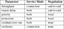
Parameter Service Mode Negotiation throughput connection end-to-end transit delay both end-to-end priority both local protection both local residual error rate both none resilience connection none
5.2.1 Throughput
Throughput is a connection-mode QoS parameter that has end-to-end
significance. It is defined as the total number of DLSDU bits
successfully transferred by a DL_DATA_REQ/DL_DATA_IND primitive
sequence divided by the input/output time, in seconds, for that sequence.
Successful transfer of a DLSDU is defined to occur when the
DLSDU is delivered to the intended user without error, in proper
sequence, and before connection termination by the receiving DLS user. The
input/output time for a DL_DATA_REQ/DL_DATA_IND primitive sequence
is the greater of:
- the time between the first and last
DL_DATA_REQin a sequence; and - the time between the first and last
DL_DATA_INDin the sequence.
Throughput is only meaningful for a sequence of complete DLSDUs. Throughput is specified and negotiated for the transmit and receive directions independently at connection establishment. The throughput specification defines the target and minimum acceptable values for a connection. Each specification is an average rate. The DLS user can delay the receipt or sending of DLSDUs. The delay caused by a DLS user is not included in calculating the average throughput values.
Parameter Format
This typedef is used to negotiate the transmit and receive throughput values.
- dl_target_value
specifies the desired throughput value for the connection in bits/second.
- dl_accept_value
specifies the minimum acceptable throughput value for the connection in bits/second.
5.2.2 Transit Delay
Connection and connectionless modes can specify a transit delay, which indicates
the elapsed time between a
DL_DATA_REQ
or
DL_UNITDATA_REQ
primitive and the corresponding
DL_DATA_IND
or
DL_UNITDATA_IND
primitive. The elapsed time is only computed for DLSDUs successfully
transferred, as described previously for throughput.
In connection mode, transit delay is negotiated on an end-to-end basis during
connection establishment. For each connection, transit delay is negotiated for
the transmit and receive directions separately by specifying the target value
and maximum acceptable value. For connectionless-mode service, a DLS user selects
a particular value within the supported range using the
DL_UDQOS_REQ
primitive, and the value may be changed for each DLSDU submitted for
connectionless transmission. The transit delay for an individual
DLSDU may be
increased if the receiving DLS user flow controls the interface. The average
and maximum transit delay values exclude any DLS user flow control of the
interface. The values are specified in milliseconds, and assume a
DLSDU size of
128 octets.
Parameter Format
This typedef is used to negotiate the transmit and receive transit delay values.
- dl_target_value
specifies the desired transit delay value.
- dl_accept_value
specifies the maximum acceptable transit delay value.
5.2.3 Priority
Priority is negotiated locally between each DLS user and the DLS provider in connection-mode service, and can also be specified for connectionless-mode service. The specification of priority is concerned with the relationship between connections or the relationship between connectionless data transfer requests. The parameter specifies the relative importance of a connection with respect to:
- the order in which connections are to have their QoS degraded, if necessary; and
- the order in which connections are to be released to recover resources, if necessary;
For connectionless-mode service, the parameter specifies the relative importance of unitdata objects with respect to gaining use of shared resources.
For connection-mode service, each DLS user negotiates a particular priority
value with the DLS provider during connection establishment. The value is
specified by a minimum and a maximum within a given range. For
connectionless-mode service, a DLS user selects a particular priority value
within the supported range using the
DL_UDQOS_REQ
primitive, and the value may be changed for each DLSDU submitted for
connectionless transmission. This parameter only has meaning in the context of
some management entity or structure able to judge relative importance. The
priority has local significance only, with a value of zero being the highest
priority and 100 being the lowest priority.
Parameter Format
- dl_min
specifies the minimum acceptable priority.
- dl_max
specifies the maximum desired priority.
5.2.4 Protection
Protection is negotiated locally between each DLS user and the DLS provider in connection-mode service, and can also be specified for connectionless-mode service. Protection is the extent to which a DLS provider attempts to prevent unauthorized monitoring or manipulation of DLS user-originated information. Protection is specified by a minimum and maximum protection option within the following range of possible protection options:
DL_NONEDLS provider will not protect any DLS user data
DL_MONITORDLS provider will protect against passive monitoring
DL_MAXIMUMDLS provider will protect against modification, replay, addition, or deletion of DLS user data
For connection-mode service, each DLS user negotiates a particular value with
the DLS provider during connection establishment. The value is specified by a
minimum and a maximum within a given range. For connectionless-mode service, a
DLS user selects a particular value within the supported range using
the
DL_UDQOS_REQ
primitive, and the value may be changed for each DLSDU submitted for
connectionless transmission. Protection has local significance only.
Parameter Format
- dl_min
specifies the minimum acceptable protection.
- dl_max
specifies the maximum desired protection.
5.2.5 Residual Error Rate
Residual error rate is the ratio of total incorrect, lost and duplicate DLSDUs to the total DLSDUs transferred between DLS users during a period of time. The relationship between these quantities is defined below:
       DLSDUl + DLSDUi + DLSDUe
RER = ---------------------------
             DLSDUtot
where
- DLSDUtot
= total DLSDUs transferred, which is the total of DLSDUl, DLSDUi, DLSDUe, and correctly received DLSDUs.
- DLSDUe
= DLSDUs received 2 or more times.
- DLSDUi
= incorrectly received DLSDUs.
- DLSDUl
= DLSDUs sent, but not received.
Parameter Format
long dl_residual_error;
The residual error value is scaled by a factor of 1,000,000, since the parameter is stored as a long integer in the QoS data structures. Residual error rate is not a negotiated QoS parameter. Its value is determined by procedures outside the definition of DLPI. It is assumed to be set by an administrative mechanism, which is informed of the value by network management.
5.2.6 Resilience
Resilience is meaningful in connection mode only, and represents the probability of either: DLS provider-initiated disconnects or DLS provider-initiated resets during a time interval of 10,000 seconds on a connection. Resilience is not a negotiated QoS parameter. Its value is determined by procedures outside the definition of DLPI. It is assumed to be set by an administrative mechanism, which is informed of the value by network management.
Parameter Format
- dl_disc_prob
specifies the probability of receiving a provider-initiated disconnect, scaled by 10000.
- dl_reset_prob
specifies the probability of receiving a provider-initiated reset, scaled by 10000.
5.3 QOS Data Structures
To simplify the definition of the primitives containing QoS parameters
and the discussion of QoS negotiation, the QoS parameters
are organized into four structures. This section defines the structures and
indicates which structures apply to which primitives. Each structure is tagged
with a type field contained in the first four bytes of the structure, similar to
the tagging of primitives. The type field has been defined because of the
current volatility of QoS parameter definition within the
international standards bodies. If new QoS parameter sets are defined
in the future for the data link layer, the type field will enable DLPI to
accommodate these sets without breaking existing DLS user or provider
implementations. However, DLS user and provider software should be cognizant of
the possibility that new QoS structure types may be defined in future
issues of the DLPI specification. If a DLS provider receives a structure type
that it does not understand in a given primitive, the error [DL_BADQOSTYPE]
should be returned to the DLS user in a DL_ERROR_ACK primitive.
Currently the following QoS structure types are defined:
DL_QOS_CO_RANGE1-
QoS range structure for connection-mode service for Issue 1 of DLPI
DL_QOS_CO_SEL1-
QoS selection structure for connection-mode service for Issue 1 of DLPI
DL_QOS_CL_RANGE1-
QoS range structure for connectionless-mode service for Issue 1 of DLPI
DL_QOS_CL_SEL1-
QoS selection structure for connectionless-mode service for Issue 1 of DLPI
The syntax and semantics of each structure type is presented in the remainder of this section.
5.3.1 Structure DL_QOS_CO_RANGE1
Structure type
DL_QOS_CO_RANGE1
enables a DLS user and DLS provider to pass
between them a range of QoS parameter values in the connection-mode service. The
format of this structure type is:
typedef struct {
        ulong dl_qos_type;
        dl_through_t dl_rcv_throughput;
        dl_transdelay_t dl_rcv_trans_delay;
        dl_through_t dl_xmt_throughput;
        dl_transdelay_t dl_xmt_trans_delay;
        dl_priority_t dl_priority;
        dl_protect_t dl_protection;
        long dl_residual_error;
        dl_resilience_t dl_resilience;
} dl_qos_co_range1_t;
where the value of dl_qos_type is
DL_QOS_CO_RANGE1.
The fields of this structure correspond to the parameters defined in QOS Parameter Definitions. The throughput and transit delay parameters are
specified for each direction of transmission on a data link connection.
This structure type is returned in the dl_qos_range_length and
dl_qos_range_offset fields of the
DL_INFO_ACK,
and specifies the supported ranges of service quality supported by the DLS
provider. In other words, it specifies the available range of QoS parameter
values that may be specified on a
DL_CONNECT_REQ.
For the
DL_CONNECT_REQ
and
DL_CONNECT_IND
primitives, this structure specifies
the negotiable range of connection-mode QoS parameter values. See Procedures for QOS Negotiation and Selection, for the semantics of this structure in these
primitives.
5.3.2 Structure DL_QOS_CO_SEL1
Structure type
DL_QOS_CO_SEL1
conveys selected QoS parameter values for
connection-mode service between the DLS user and DLS provider. The format of
this structure type is:
typedef struct {
        ulong dl_qos_type;
        long dl_rcv_throughput;
        long dl_rcv_trans_delay;
        long dl_xmt_throughput;
        long dl_xmt_trans_delay;
        long dl_priority;
        long dl_protection;
        long dl_residual_error;
        dl_resilience_t dl_resilience;
} dl_qos_co_sel1_t;
where the value of dl_qos_type is
DL_QOS_CO_SEL1.
The fields of this structure correspond to the parameters defined in QOS Parameter Definitions. The throughput and transit delay parameters are
specified for each direction of transmission on a data link connection.
This structure type is returned in the dl_qos_length and dl_qos_offset fields of
the
DL_INFO_ACK,
and specifies the current or default QoS parameter values associated with a
stream. Default values are returned prior to connection establishment, and
currently negotiated values are returned when a connection is active on the
stream.
The structure type is used in the
DL_CONNECT_RES
to enable the responding DLS user to select particular QoS parameter values from
the available range. The
DL_CONNECT_CON
primitive returns the selected values to the calling DLS user in this structure.
See Procedures for QOS Negotiation and Selection, for the semantics of this
structure in these primitives.
5.3.3 Structure DL_QOS_CL_RANGE1
Structure type
DL_QOS_CL_RANGE1
enables a DLS user and DLS provider to pass
between them a range of QoS parameter values in the connectionless-mode service.
The format of this structure type is:
typedef struct {
        ulong dl_qos_type;
        dl_transdelay_t dl_trans_delay;
        dl_priority_t dl_priority;
        dl_protect_t dl_protection;
        long dl_residual_error;
} dl_qos_cl_range1_t;
where the value of dl_qos_type is
DL_QOS_CL_RANGE1.
The fields of this structure correspond to the parameters defined in QOS Parameter Definitions.
This structure type is returned in the dl_qos_range_length and
dl_qos_range_offset fields of the
DL_INFO_ACK,
and specifies the range of connectionless-mode QoS parameter values supported by
the DLS provider on the stream. The DLS user may select specific values from
this range using the
DL_UDQOS_REQ
primitive, as described in Procedures for QOS Negotiation and Selection.
5.3.4 Structure DL_QOS_CL_SEL1
Structure type
DL_QOS_CL_SEL1
conveys selected QoS parameter values for
connectionless-mode service between the DLS user and DLS provider. The format
of this structure type is:
typedef struct {
        ulong dl_qos_type;
        long dl_trans_delay;
        long dl_priority;
        long dl_protection;
        long dl_residual_error;
} dl_qos_cl_sel1_t;
where the value of dl_qos_type is
DL_QOS_CL_SEL1.
The fields of this structure correspond to the parameters defined in QOS Parameter Definitions.
This structure type is returned in the dl_qos_length and dl_qos__offset fields
of the
DL_INFO_ACK,
and specifies the current or default QoS parameter values associated with a
stream. Default values are returned until the DLS user issues a
DL_UDQOS_REQ
to change the values, after which the currently selected values will be
returned. The structure type is also used in the
DL_UDQOS_REQ
primitive to enable a DLS user to select particular QoS parameter values from
the supported range, as described in Procedures for QOS Negotiation and Selection.
5.4 Procedures for QOS Negotiation and Selection
This section describes the methods used for negotiating and/or selecting QoS parameter values. In the connection-mode service, some QoS parameter values may be negotiated during connection establishment. For connectionless-mode service, parameter values may be selected for subsequent data transmission.
Throughout this section, two special QoS values are referenced. These are defined for all the parameters used in QoS negotiation and selection. The values are:
DL_UNKNOWNThis value indicates that the DLS provider does not know the value for the field or does not support that parameter.
DL_QOS_DONT_CAREThis value indicates that the DLS user does not care to what value the QoS parameter is set.
These values are used to distinguish between DLS providers that support and negotiate QoS parameters and those that cannot. The following sections include the interpretation of these values during QoS negotiation and selection.
5.4.1 Connection-mode QOS Negotiation
The current connection-mode QoS parameters can be divided into three types as follows:
- Those that are negotiated end-to-end between peer DLS users and the DLS provider during connection establishment (throughput and transit delay);
- those that are negotiated locally between each DLS user and the DLS provider during connection establishment (priority and protection); and
- those that cannot be negotiated (residual error rate and resilience).
The rules for processing these three types of parameters during connection establishment are described in this section.
The current definition of most existing data link protocols does not describe a mechanism for negotiating QoS parameters during connection establishment. As such, DLPI does not require every DLS provider implementation to support QoS negotiation. If a given DLS provider implementation cannot support QoS negotiation, two alternatives are available:
- The DLS provider may specify that any or all QoS parameters are unknown.
This is indicated to the DLS user in the
DL_INFO_ACK, where the values in the QoS range field (indicated by dl_qos_range_length and dl_qos_range_offset) and the current QoS field (indicated by dl_qos_length and dl_qos_offset) of this primitive are set toDL_UNKNOWN. This value will also be indicated on theDL_CONNECT_INDandDL_CONNECT_CONprimitives. If the DLS provider does not support any QoS parameters, the QoS length field may be set to zero in each of these of these primitives. - The DLS provider may interpret QoS parameters with strictly local
significance, and their values in the
DL_CONNECT_INDprimitive will be set toDL_UNKNOWN.
A DLS user need not select a specific value for each QoS parameter. The special
QoS parameter value,
DL_QOS_DONT_CARE,
is used if the DLS user does not care what quality of service is provided for a
particular parameter. The negotiation procedures presented below explain the
exact semantics of this value during
connection establishment.
If QoS parameters are supported by the DLS provider, the provider will define a
set of default QoS parameter values that are used whenever
DL_QOS_DONT_CARE
is specified for a QoS parameter value. These default values can be defined for
all DLS users or can be defined on a per DLS user basis. The default parameter
value set is returned in the QoS field (indicated by dl_qos_length and
dl_qos_offset) of the
DL_INFO_ACK
before a DLS user negotiates QoS parameter values.
DLS provider addendum documentation must describe the known ranges of support for the QoS parameters and the default values, and also specify whether they are used in a local manner only. The following procedures are used to negotiate QoS parameter values during connection establishment.
- (1)
-
The
DL_CONNECT_REQspecifies the DLS user’s desired range of QoS values in the dl_qos_co_range1_t structure. The target and least-acceptable values are specified for throughput and transit delay, as described in Throughput, and Transit Delay. The target value is the value desired by the calling DLS user for the QoS parameters. The least acceptable value is the lowest value the calling user will accept. These values are specified separately for both the transmit and receive directions of the connection.If either value is set to
DL_QOS_DONT_CAREthe DLS provider will supply a default value, subject to the following consistency constraints:- – If
DL_QOS_DONT_CAREis specified for the target value, the value chosen by the DLS provider may not be less than the least-acceptable value. - – If
DL_QOS_DONT_CAREis specified for the least-acceptable value, the value set by the DLS provider cannot be greater than the target value. - – If
DL_QOS_DONT_CAREis specified for both the target and least-acceptable value, the DLS provider is free to select any value, without constraint, for the target and least acceptable values.
For priority and protection, the
DL_CONNECT_REQspecifies a minimum and maximum desired value as defined in Priority, and Protection. As with throughput and transit delay, the DLS user may specify a value ofDL_QOS_DONT_CAREfor either the minimum or maximum value. The DLS provider will interpret this value subject to the following consistency constraints:- – If
DL_QOS_DONT_CAREis specified for the maximum value, the value chosen by the DLS provider may not be less than the minimum value. - – If
DL_QOS_DONT_CAREis specified for the minimum value, the value set by the DLS provider cannot be greater than the maximum value. - – If
DL_QOS_DONT_CAREis specified for both the minimum and maximum values, the DLS provider is free to select any value, without constraint, for the maximum and minimum values.
The values of the residual error rate and resilience parameters in the
DL_CONNECT_REQhave no meaning and are ignored by the DLS provider.If the value of dl_qos_length in the
DL_CONNECT_REQis set to zero by the DLS user, the DLS provider should treat all QoS parameter values as if they were set toDL_QOS_DONT_CARE, selecting any value in its supported range.If the DLS provider cannot support throughput, transit delay, priority, and protection values within the ranges specified in the
DL_CONNECT_REQ, aDL_DISCONNECT_INDshould be sent to the calling DLS user. - – If
- (2)
-
If the requested ranges of values for throughput and transit delay in the
DL_CONNECT_REQare acceptable to the DLS provider, the QoS parameters will be adjusted to values the DLS provider will support. Only the target value may be adjusted, and it is set to a value the DLS provider is willing to provide (which may be of lower QoS than the target value). The least-acceptable value cannot be modified. The updated QoS range is then sent to the called DLS user in the dl_qos_co_range1_t structure of theDL_CONNECT_IND, where it is interpreted as the available range of service.If the requested range of values for priority and protection in the
DL_CONNECT_REQis acceptable to the DLS provider, an appropriate value within the range is selected and saved for each parameter; these selected values will be returned to the DLS user in the correspondingDL_CONNECT_CONprimitive. Because priority and protection are negotiated locally, theDL_CONNECT_INDwill not contain values selected during negotiation with the calling DLS user. Instead, the DLS provider will offer a range of values in theDL_CONNECT_INDthat will be supported locally for the called DLS user.The DLS provider will also include the supported values for residual error rate and resilience in the
DL_CONNECT_INDthat is passed to the called DLS user.If the DLS provider does not support negotiation of throughput, transit delay, priority, or protection, a value of
DL_UNKNOWNshould be set in the least-acceptable, target, minimum, and maximum value fields of theDL_CONNECT_IND. Also, if the DLS provider does not support any particular QoS parameter,DL_UNKNOWNshould be specified in all value fields for that parameter. If the DLS provider does not support any QoS parameters, the value of dl_qos_length may be set to zero in theDL_CONNECT_IND. - (3)
-
Upon receiving the
DL_CONNECT_IND, the called DLS user examines the QoS parameter values and selects a specific value from the proffered range of the throughput, transit delay, priority, and protection parameters. If the called DLS user does not agree on values in the given range, the connection should be refused with aDL_DISCONNECT_REQprimitive. Otherwise, the selected values are returned to the DLS provider in the dl_qos_co_sel1_t structure of theDL_CONNECT_RESprimitive.The values of residual error rate and resilience in the
DL_CONNECT_RESare ignored by the DLS provider. These parameters may not be negotiated by the called DLS user. The selected values of throughput and transit delay are meaningful, however, and are adopted for the connection by the DLS provider. Similarly, the selected priority and protection values are adopted with local significance for the called DLS user.If the user specifies
DL_QOS_DONT_CAREfor either throughput, transit delay, priority, or protection on theDL_CONNECT_RES, the DLS provider will select a value from the range specified for that parameter in theDL_CONNECT_INDprimitive. Also, a value of zero in the dl_qos_length field of theDL_CONNECT_RESis equivalent toDL_QOS_DONT_CAREfor all QoS parameters. - (4)
-
Upon completion of connection establishment, the values of throughput and transit delay as selected by the called DLS user are returned to the calling DLS user in the dl_qos_co_sel1_t structure of the
DL_CONNECT_CONprimitive. The values of priority and protection that were selected by the DLS provider from the range indicated in theDL_CONNECT_REQwill also be returned in theDL_CONNECT_CON. This primitive will also contain the values of residual error rate and resilience associated with the newly established connection. The DLS provider also saves the negotiated QoS parameter values for the connection, so that they may be returned in response to aDL_INFO_REQprimitive.As with
DL_CONNECT_IND, if the DLS provider does not support negotiation of throughput, transit delay, priority, or protection, a value ofDL_UNKNOWNshould be returned in the selected value fields. Furthermore, if the DLS provider does not support any particular QoS parameter,DL_UNKNOWNshould be specified in all value fields for that parameter, or the value of dl_qos_length may be set to zero in theDL_CONNECT_CONprimitive.
5.4.2 Connectionless-mode QOS Selection
This section describes the procedures for selecting QoS parameter values that will be associated with the transmission of connectionless data or acknowledged connectionless data.
As with connection-mode protocols, the current definition of most existing
(acknowledged) connectionless data link protocols does not define a quality of
service concept. As such, DLPI does not require every DLS provider
implementation to support QoS parameter selection. The DLS provider may specify
that any or all QoS parameters are unsupported. This is indicated to the DLS user
in the
DL_INFO_ACK,
where the values in the supported range field (indicated by dl_qos_range_length
and dl_qos_range_offset)and the current QoS field (indicated by dl_qos_length
and dl_qos_offset) of this primitive are set to
DL_UNKNOWN.
If the DLS provider supports no QoS parameters, the QoS length fields in the
DL_INFO_ACK
may be set to zero. If the DLS provider supports QoS parameter selection, the
DL_INFO_ACK
primitive will specify the supported range of parameter values for transit
delay, priority, protection and residual error rate. Default values are also
returned in the
DL_INFO_ACK.
For each
DL_UNITDATA_REQ/DL_DATA_ACK_REQ,
the DLS provider should apply the currently selected QoS parameter values to the
transmission. If no values have been selected, the default values should be
used.
At any point during data transfer, the DLS user may issue a
DL_UDQOS_REQ
primitive to select new values for the transit delay, priority, and protection
parameters. These values are selected using the dl_qos_cl_sel1_t structure.
The residual error rate parameter is ignored by this primitive and cannot be
set by a DLS user.
In the
DL_UDQOS_REQ,
the DLS user need not require a specific value for every QoS parameter.
DL_QOS_DONT_CARE
may be specified if the DLS user does not care what quality of service is
provided for a particular parameter. When specified, the DLS provider should
retain the current (or default if no previous selection has occurred) value for
that parameter.
Appendix A Optional Primitives to perform Essential Management Functions
This appendix presents the optional primitives to perform essential management functions. The management functions supported are get and set of physical address, and statistics gathering.
A.1 Message DL_PHYS_ADDR_REQ (dl_phys_addr_req_t)
This primitive requests the DLS provider to return either the default (factory) or the current value of the physical address associated with the stream depending upon the value of the address type selected in the request.
Message Format
The message consists of one M_PROTO message block containing the structure shown
below:
Parameters
- dl_primitive
conveys
DL_PHYS_ADDR_REQ;- dl_addr_type
conveys the type of address requested - factory physical address or current physical address
DL_FACT_PHYS_ADDRfactory physical address DL_CURR_PHYS_ADDR current physical address
State
The message is valid in any attached state in which a local acknowledgment is
not pending. For a style 2provider, this would be after a PPA is attached using
the
DL_ATTACH_REQ.
For a Style 1 provider, the PPA is implicitly attached after the stream is
opened.
New State
The resulting state is unchanged.
Response
The provider responds to the request with a
DL_PHYS_ADDR_ACK
if the request is supported. Otherwise, a
DL_ERROR_ACK
is returned.
Reasons for failure
[DL_NOTSUPPORTED]Primitive is known, but not supported by the DLS Provider.
[DL_OUTSTATE]The primitive was issued from an invalid state.
A.2 Message DL_PHYS_ADDR_ACK (dl_phys_addr_ack_t)
This primitive returns the value for the physical address to the link user in
response to a
DL_PHYS_ADDR_REQ.
Message Format
The message consists of M_PCPROTO message block containing the following
structure:
typedef struct {
        ulong dl_primitive;
        ulong dl_addr_length;
        ulong dl_addr_offset;
} dl_phys_addr_ack_t;
Parameters
- dl_primitive
conveys
DL_PHYS_ADDR_ACK- dl_addr_length
conveys length of the physical address. dl_addr_offset conveys the offset from the beginning of the
M_PCPROTOmessage block.
State
The message is valid in any state in response to a
DL_PHYS_ADDR_REQ.
New State
The resulting state is unchanged.
A.3 Message DL_SET_PHYS_ADDR_REQ (dl_set_phys_addr_req_t)
Sets the physical address value for all streams for that provider for a particular PPA.
Message Format
The message consists of M_PROTO message block which contains the following
structure:
typedef struct {
        ulong dl_primitive;
        ulong dl_addr_length;
        ulong dl_addr_offset;
} dl_set_phys_addr_req_t;
Parameters
- dl_primitive
conveys
DL_SET_PHYS_ADDR_REQ- dl_addr_offset
conveys the offset from the beginning of the
M_PROTOmessage block dl_addr_length conveys the length of the requested hardware address
State
The message is valid in any attached state in which a local acknowledgment is
not pending. For a Style 2provider, this would be after a PPA is attached using
the
DL_ATTACH_REQ.
For a Style 1 provider, the PPA is implicitly attached after the stream is
opened.
New State
The resulting state is unchanged
Response
The provider responds to the request with a
DL_OK_ACK
on successful completion. Otherwise, a
DL_ERROR_ACK
is returned.
Reasons for failure
[DL_BADADDR]The address information was invalid or was in an incorrect format.
[DL_NOTSUPPORTED]Primitive is known, but not supported by the DLS Provider.
[DL_SYSERR]A system error has occurred
[DL_OUTSTATE]The primitive was issued from an invalid state.
[DL_BUSY]One or more streams for that particular PPA are in the bound (
DL_IDLE) state.
A.4 Message DL_GET_STATISTICS_REQ (dl_get_statistics_req_t)
Directs the DLS provider to return statistics
Message Format
The message consists of one M_PROTO message block containing the structure shown
below:
Parameters
- dl_primitive
conveys
DL_GET_STATISTICS_REQ
State
The message is valid in any state in which a local acknowledgment is not pending.
New State
The resulting state is unchanged
Response
The DLS Provider responds to this request with a
DL_GET_STATISTICS_ACK if the
primitive is supported. Otherwise, a
DL_ERROR_ACK
is returned.
Reasons for failure
[DL_NOTSUPPORTED]Primitive is known but not supported by the DLS Provider.
A.5 Message DL_GET_STATISTICS_ACK (dl_get_statistics_ack_t)
Returns statistics in response to the
DL_GET_STATISTICS_REQ.
The contents of the statistics block is defined in the DLS Provider specific
addendum.
Message Format
The message consists of one M_PCPROTO message block containing the structure
shown below:
typedef struct {
        ulong dl_primitive;
        ulong dl_stat_length;
        ulong dl_stat_offset;
} dl_get_statistics_ack_t;
Parameters
- dl_primitive
conveys
DL_GET_STATISTICS_ACK- dl_stat_len
conveys the length of the statistics structure dl_stat_offset conveys the offset from the beginning of the M_PCROTO message block where the statistics information resides.
State
The message is valid in any state in which a local acknowledgment is not pending.
New State
The resulting state is unchanged
Appendix B Allowable Sequence of DLPI Primitives
This appendix presents the allowable sequence of DLPI primitives. The sequence is described using a state transition table that defines possible states as viewed by the DLS user. The state transition table describes transitions based on the current state of the interface and a given DLPI event. Each transition consists of a state change and possibly an interface action. The states, events, and related transition actions are described below, followed by the state transition table itself.
B.1 DLPI States
The following table describes the states associated with DLPI. It presents the
state name used in the state transition table, the corresponding DLPI state name
used throughout this specification, a brief description of the state, and an
indication of whether the state is valid for connection-oriented data link
service
(DL_CODLS),
connectionless data link service
(DL_CLDLS),
acknowledged connectionless data link service
(DL_ACLDLS)
or all.
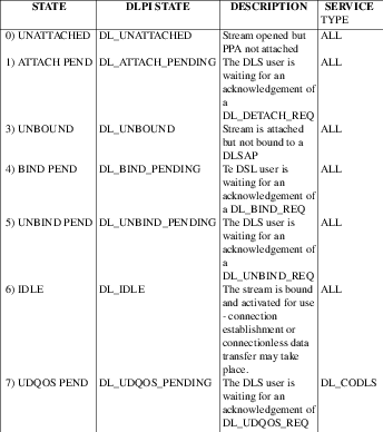
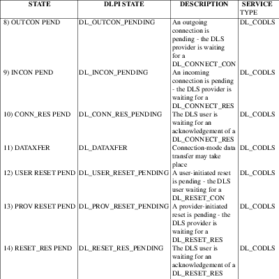
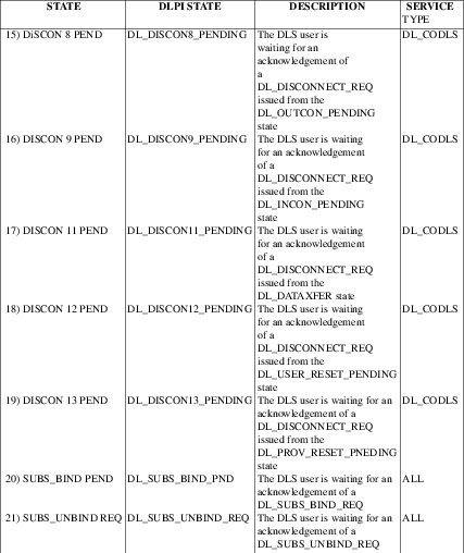
B.2 Variables and Actions for State Transition Table
The following tables describe variables and actions used to describe the
DLPI
state transitions. The variables are used to distinguish various uses of the
same DLPI primitive. For example, a
DL_CONNECT_RES
causes a different state transition depending on the current number of
outstanding connect indications. To distinguish these different connect
response events, a variable is used to track the number of outstanding connect
indications.
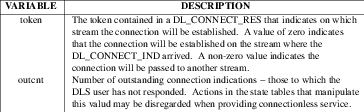
The actions represent steps the DLS provider must take during certain state transitions to maintain the interface state. When an action is indicated in the state transition table, the DLS provider should change the state as indicated and perform the specified action.
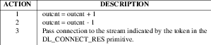
B.3 DLPI User-Originated Events
The following table describes events initiated by the DLS user that correspond
to the various request and response primitives of DLPI. The table presents the
event name used in the state transition table, a brief description of the event
(including the corresponding DLPI primitive), and an indication of whether
the event is valid for connection-oriented data link service
(DL_CODLS),
connectionless data link service
(DL_CLDLS),
acknowledged connectionless data link service
(DL_ACLDLS)
or all.
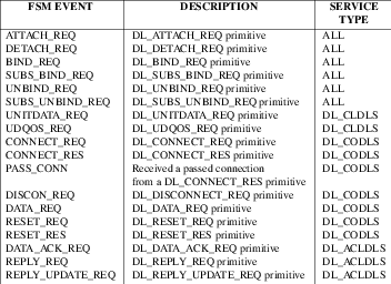
B.4 DLPI Provider-Originated Events
The following table describes the events initiated by the DLS provider that
correspond to the various indication, confirmation, and acknowledgment
primitives of DLPI. The table presents the event name used in the state
transition table, a brief description of the event (including the corresponding
DLPI primitive), and an indication of whether the event is valid for
connection-oriented data link service
(DL_CODLS),
connectionless data link service
(DL_CLDLS),
acknowledged connectionless service
(DL_ACDLS)
or all.
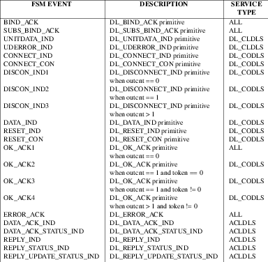
B.5 DLPI State Transition Table
Table 7, Table 8, Table 9 and Table 10 describe the DLPI state transitions. Each column represents a state of DLPI (Table 2a) and each row represents a DLPI event (Table 5 and Table 6). The intersecting transition cell defines the resulting state transition (i.e. next state) and associated actions, if any, that must be executed by the DLS provider to maintain the interface state. Each cell may contain the following:
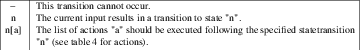
The
DL_INFO_REQ,
DL_INFO_ACK,
DL_TOKEN_REQ, and
DL_TOKEN_ACK primitives
are excluded from the state transition table because they can be issued from many
states and, when fully processed, do not cause a state transition to occur.
However, the DLS user may not issue a
DL_INFO_REQ or
DL_TOKEN_REQ if any local
acknowledgments are pending. In other words, these two primitives may not be
issued until the DLS user receives the acknowledgment for any previously issued
primitive that is expecting local positive acknowledgment. Thus, these
primitives may not be issued from the
DL_ATTACH_PENDING,
DL_DETACH_PENDING,
DL_BIND_PENDING,
DL_SUBS_BIND_PND,
DL_SUBS_UNBIND_PND,
DL_UNBIND_PENDING,
DL_UDQOS_PENDING,
DL_CONN_RES_PENDING,
DL_RESET_RES_PENDING,
DL_DISCON8_PENDING,
DL_DISCON9_PENDING,
DL_DISCON11_PENDING,
DL_DISCON12_PENDING, or
DL_DISCON13_PENDING states. Failure to
comply by this restriction may result in loss of primitives at the stream head
if the DLS user is a user process. Once a
DL_INFO_REQ or
DL_TOKEN_REQ
has been issued, the DLS provider must respond with the appropriate
acknowledgment primitive.
The following rules apply to the maintenance of DLPI state:
- The DLS provider is responsible for keeping a record of the state of the
interface as viewed by the DLS user, to be returned in the
DL_INFO_ACK. - The DLS provider may never generate a primitive that places the interface out of state (i.e. would correspond to a "-" cell entry in the state transition table below).
- If the DLS provider generates a STREAMS
M_ERRORmessage upstream, it should free any further primitives processed by it’s write side put or service procedure. - The close of a stream is considered an abortive action by the DLS user,
and may be executed from any state. The DLS provider must issue appropriate
indications to the remote DLS user when a close occurs. For example, if the
DLPI
state is
DL_DATAXFER, aDL_DISCONNECT_INDshould be sent to the remote DLS user. The DLS provider should free any resources associated with that stream and reset the stream to its unopened condition. The following points clarify the state transition table. - If the DLS provider supports connection-mode service, the value of the outcnt state variable must be initialized to zero for each stream when that stream is first opened.
- The initial and final state for a style 2 DLS provider is
DL_UNATTACHED. However, because a style 1 DLS provider implicitly attaches a PPA to a stream when it is opened, the initial and final DLPI state for a style 1 provider isDL_UNBOUND. The DLS user should not issueDL_ATTACH_REQorDL_DETACH_REQprimitives to a style 1 DLS provider. - A DLS provider may have multiple connect indications outstanding (i.e. the
DLS user has not responded to them) at one time (see Multi-threaded Connection Establishment). As the state transition table points out, the stream on which
those indications are outstanding will remain in the
DL_INCON_PENDINGstate until the DLS provider receives a response for all indications. - The DLPI state associated with a given stream may be transferred to
another stream only when the
DL_CONNECT_RESprimitive indicates this behavior. In this case, the responding stream (where the connection will be established) must be in theDL_IDLEstate. This state transition is indicated by the PASS_CONN event in Table 9. - The labeling of the states
DL_PROV_RESET_PENDINGandDL_USER_RESET_PENDINGindicate the party that started the local interaction, and does not necessarily indicate the originator of the reset procedure. - A
DL_DATA_REQprimitive received by the DLS provider in the stateDL_PROV_RESET_PENDING(i.e. after aDL_RESET_INDhas been passed to the DLS user) or the stateDL_IDLE(i.e. after a data link connection has been released) should be discarded by the DLS provider. - A
DL_DATA_INDprimitive received by the DLS user after the user has issued aDL_RESET_REQshould be discarded. To ensure accurate processing of DLPI primitives, the DLS provider must adhere to the following rules concerning the receipt and generation of STREAMSM_FLUSHmessages during various state transitions. - The DLS provider must be ready to receive
M_FLUSHmessages from upstream and flush it’s queues as specified in the message. - The DLS provider must issue an
M_FLUSHmessage upstream to flush both the read and write queues after receiving a successfulDL_UNBIND_REQprimitive but before issuing theDL_OK_ACK. - If an incoming disconnect occurs when the interface is in the
DL_DATAXFER,DL_USER_RESET_PENDING, orDL_PROV_RESET_PENDINGstate, the DLS provider must send up anM_FLUSHmessage to flush both the read and write queues before sending up aDL_DISCONNECT_IND. - If a
DL_DISCONNECT_REQis issued in theDL_DATAXFER,DL_USER_RESET_PENDING, orDL_PROV_RESET_PENDINGstates, the DLS provider must issue anM_FLUSHmessage upstream to flush both the read and write queues after receiving the successfulDL_DISCONNECT_REQbut before issuing theDL_OK_ACK. - If a reset occurs when the interface is in the
DL_DATAXFERorDL_USER_RESET_PENDINGstate, the DLS provider must send up anM_FLUSHmessage to flush both the read and write queues before sending up aDL_RESET_INDorDL_RESET_CON.
The following table presents the allowed sequence of DLPI primitives for the common local management phase of communication.
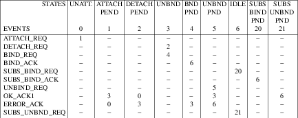
The following table presents the allowed sequence of DLPI primitives for the connectionless data transfer phase.
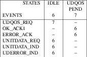
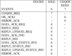
The following table presents the allowed sequence of DLPI primitives for the connection establishment phase of connection mode service.
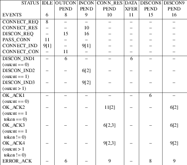
The following table presents the allowed sequence of DLPI primitives for the connection mode data transfer phase.
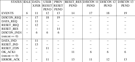
Appendix C Precedence of DLPI Primitives
This appendix presents the precedence of DLPI primitives relative to one another. Two queues are used to describe DLPI precedence rules. One queue contains DLS user-originated primitives and corresponds to the STREAMS write queue of the DLS provider. The other queue contains DLS provider-originated primitives and corresponds to the STREAMS read queue of the DLS user. The DLS provider is responsible for determining precedence on its write queue and the DLS user is responsible for determining precedence on its read queue as indicated in the precedence tables below. For each precedence table, the rows (labeled PRIM X) correspond to primitives that are on the given queue and the columns (labeled PRIM Y) correspond to primitives that are about to be placed on that queue. Each pair of primitives (PRIM X, PRIM Y) may be manipulated resulting in:
- Change of order, where the order of a pair of primitives is reversed if, and only if, the second primitive in the pair (PRIM Y) is of a type defined to be able to advance ahead of the first primitive in the pair (PRIM X).
- Deletion, where a primitive (PRIM X) may be deleted if, and only if, the primitive that follows it(PRIM Y) is defined to be destructive with respect to that primitive. Destructive primitives may always be added to the queue. Some primitives may cause both primitives in the pair to be destroyed. The precedence rules define the allowed manipulations of a pair of DLPI primitives. Whether these actions are performed is the choice of the DLS provider for user-originated primitives and the choice of the DLS user for provider-originated primitives.
C.1 Write Queue Precedence
The following table presents the precedence rules for DLS user-originated primitives on the DLS provider’s STREAMS write queue. It assumes that only non-local primitives (i.e. those that generate protocol data units to a peer DLS user) are queued by the DLS provider.
For connection establishment primitives, this table represents the possible pairs of DLPI primitives when connect indications/responses are single-threaded. For the multi-threading scenario, the following rules apply:
- A
DL_CONNECT_RESprimitive has no precedence over either aDL_CONNECT_RESor aDL_DISCONNECT_REQprimitive that is associated with another connection correlation number (dl_correlation), and should therefore be placed on the queue behind such primitives. - Similarly, a
DL_DISCONNECT_REQprimitive has no precedence over either aDL_CONNECT_RESor aDL_DISCONNECT_REQprimitive that is associated with another connection correlation number, and should therefore be placed on the queue behind such primitives. Notice, however, that aDL_DISCONNECT_REQdoes have precedence over aDL_CONNECT_RESprimitive that is associated with the same correlation number (this is indicated in the table below).
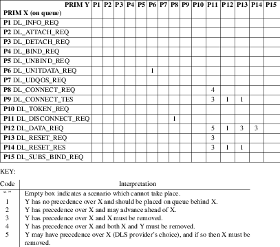
C.2 Read Queue Precedence
The following table presents the precedence rules for DLS provider-originated primitives on the DLS user’s STREAMS read queue.
For connection establishment primitives, this table represents the possible pairs of DLPI primitives when connect indications/responses are single-threaded. For the multi-threading scenario, the following rules apply:
- A
DL_CONNECT_INDprimitive has no precedence over either aDL_CONNECT_INDor aDL_DISCONNECT_INDprimitive that is associated with another connection correlation number (dl_correlation), and should therefore be placed on the queue behind such primitives. - Similarly, a
DL_DISCONNECT_INDprimitive has no precedence over either aDL_CONNECT_INDor aDL_DISCONNECT_INDprimitive that is associated with another connection correlation number, and should therefore be placed on the queue behind such primitives. - A
DL_DISCONNECT_INDdoes have precedence over aDL_CONNECT_INDprimitive that is associated with the same correlation number (this is indicated in the table below). If aDL_DISCONNECT_INDis about to be placed on the DLS user’s read queue, the user should scan the read queue for a possibleDL_CONNECT_INDprimitive with a matching correlation number. If a match is found, both theDL_DISCONNECT_INDand matchingDL_CONNECT_INDshould be removed.
If the DLS user is a user-level process, it’s read queue is the stream head read
queue. Because a user process has no control over the placement of DLS
primitives on the stream head read queue, a DLS user cannot straightforwardly
initiate the actions specified in the following precedence table. Except for
the connection
establishment scenario, the DLS user can ignore the precedence rules defined in
the table below. This is equivalent to saying the DLS user’s read queue
contains at most one primitive. The only exception to this rule is the
processing of connect indication/response primitives. A problem arises if a
user issues a DL_CONNECT_RES primitive when a DL_DISCONNECT_IND is
on the stream head read queue. The DLS provider will not be expecting the
connect response because it has forwarded the disconnect indication to the DLS
user and is in the DL_IDLE state. It will therefore generate an error
upon seeing the DL_CONNECT_RES. To avoid this error, the DLS user should
not respond to a DL_CONNECT_IND primitive if the stream head read queue
is not empty. The assumption here is a nonempty queue may be holding a
disconnect indication that is associated with the connect indication that is
being processed.
When connect indications/responses are single-threaded, a non-empty read queue
can only contain a DL_DISCONNECT_IND, which must be associated with the
outstanding DL_CONNECT_IND. This DL_DISCONNECT_IND primitive
indicates to the DLS user that the DL_CONNECT_IND is to be removed. The
DLS user should not issue a response to the DL_CONNECT_IND if a
DL_DISCONNECT_IND is received. The multi-threaded scenario is slightly
more complex, because multiple DL_CONNECT_IND and
DL_DISCONNECT_IND primitives may be interspersed on the stream head read
queue. In this scenario, the DLS user should retrieve all indications on the
queue before responding to a given connect indication. If a queued primitive is
a DL_CONNECT_IND, it should be stored by the user process for eventual
response. If a queued primitive is a DL_DISCONNECT_IND, it should be
matched (using the correlation number) against any stored connect indications.
The matched connect indication should then be removed, just as is done in the
single-threaded scenario.
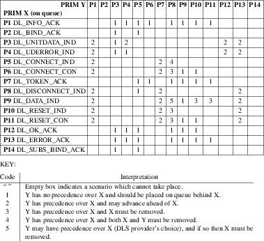
Appendix D Glossary of DLPI Terms and Acronyms
D.1 Acronyms
The following acronyms apply to the Data Link Provider Interface:
- DLPI
-
Data Link Provider Interface
- DLS
-
Data Link Service
- DLSAP
-
Data Link Service Access Point
- DLSDU
-
Data Link Service Data Unit
- ISO
-
International Organization for Standardization
- OSI
-
Open Systems Interconnection
- PPA
-
Physical Point of Attachment
- QOS
-
Quality of Service
D.2 Terms
The following terms apply to the Data Link Provider Interface:
- Called DLS user
-
The DLS user in connection mode that processes requests for connections from other DLS users.
- Calling DLS user
-
The DLS user in connection mode that initiates the establishment of a data link connection.
- Communication endpoint
-
The local communication channel between a DLS user and DLS provider.
- Connection establishment
-
The phase in connection mode that enables two DLS users to create a data link connection between them.
- Connectionless mode
-
A mode of transfer in which data is passed from one user to another in self-contained units with no logical relationship required among the units.
- Connection management stream
-
A special stream that will receive all incoming connect indications destined for DLSAP addresses that are not bound to any other streams associated with a particular PPA.
- Connection mode
-
A circuit-oriented mode of transfer in which data is passed from one user to another over an established connection in a sequenced manner.
- Connection release
-
The phase in connection mode that terminates a previously established data link connection.
- Data link service data unit
-
A grouping of DLS user data whose boundaries are preserved from one end of a data link connection to the other.
- Data transfer
-
The phase in connection and connectionless modes that supports the transfer of data between two DLS users.
- DLSAP
-
An point at a DLS user attaches itself to a DLS provider to access data link services.
- DLSAP address
-
An identifier used to differentiate and locate specific DLS user access points to a DLS provider.
- DLS provider
-
The data link layer protocol that provides the services of the Data Link Provider Interface.
- DLS user
-
The user-level application or user-level or kernel-level protocol that accesses the services of the data link layer.
- Local management
-
The phase in connection and connectionless modes in which a DLS user initializes a stream and binds a DLSAP to the stream. Primitives in this phase generate local operations only.
- PPA
-
The point at which a system attaches itself to a physical communications medium.
- PPA identifier
-
An identifier of a particular physical medium over which communication transpires.
- Quality of service
-
Characteristics of transmission quality between two DLS users.
Appendix E Guidelines for Protocol Independent DLS Users
DLPI enables a DLS user to be implemented in a protocol-independent manner such that the DLS user can operate over many DLS providers without changing the DLS user software. DLS user implementors must adhere to the following guidelines, however, to achieve this independence.
- The protocol-specific service limits returned in the
DL_INFO_ACKprimitive (e.g. dl_max_sdu) mustn’t be exceeded. The DLS user should access these limits and adhere to them while interacting with the DLS provider. - Protocol-specific DLSAP address and PPA identifier formats should be hidden from DLS user software. Hard-coded addresses and identifiers must be avoided. The DLS user should retrieve the necessary information from some other entity (such as a management entity or a higher layer protocol entity) and insert it without inspection into the appropriate primitives.
- The DLS user should not be written to a specific style of DLS provider
(i.e. style 1 vs. style 2). The
DL_INFO_ACKreturns sufficient information to identify which style of provider has been accessed, and the DLS user should perform (or not perform) aDL_ATTACH_REQaccordingly. - The names of devices should not be hard-coded into user-level programs that access a DLS provider.
- The DLS user should access the dl_service_mode field of the
DL_INFO_ACKprimitive to determine whether connection or connectionless services are available on a given stream.
Appendix F Required Information for DLS Provider-Specific Addenda
DLPI is a general interface to the services of any DLS provider. However, areas have been documented in this specification where DLS provider-specific information can be conveyed and interpreted. This appendix summarizes all provider-specific issues as an aid to developers of DLS provider implementations. As such, it forms a checklist of required information that should be documented in some manner as part of the provider implementation. The areas DLS provider-specific addendum documentation must address are:
- DLSAP Address Space
- PPA Access and Control
- Quality of Service
-
DL_INFO_ACKValues - Supported Services
For each area listed, a brief description of the provider-specific item(s) associated with it will be presented, including references to the appropriate section in this specification.
DLSAP Address Space (Sections 2.3.2 and 4.1.6) The format of a DLSAP address is
specific to each DLS provider, as is the management of that address space.
There are no restriction on the format or style of a DLSAP address. As such, a
specific implementation should document the format, size, and restrictions of a
DLSAP address, as well as information on how the address space is managed. For
example, DLPI enables a DLS user to choose a specific DLSAP address to be bound
to a stream, but a given implementation may pre-associate addresses with streams
based, for example, on the major/minor device number of the stream. In this
case, the DLS user could only retrieve the address associated with a stream. If
the DLS provider enables a user to select the DLSAP address for a stream, the
implementation must document the contents of the dl_sap field in the
DL_BIND_REQ. This field must contain sufficient information to enable
the DLS provider to determine the chosen DLSAP address. This may be the full
DLSAP address (if it is not larger than sizeof(ulong)), or some distinguishable
part of that address. For example, an implementation of a DLS provider
conforming to the ISO 8802/2 address space might allow the DSAP or SSAP portion
of the DLSAP address to be specified here, where the MAC address portion remains
constant over all DLSAP addresses managed by that provider.
Another aspect of address management is whether the provider supports the
ability to dynamically allocate DLSAPs other than the requested DLSAP in a
DL_BIND_REQ. Restrictions on DLSAPs might cover the range of supported
DLSAP values, services
provided by a DLSAP, connection management, and multiplexing. An example of
connection management restrictions is the number of connections allowed per
DLSAP. Examples of multiplexing restrictions include the number of DLSAPs per
PPA, and requirements that certain DLSAPs are attached to specific PPAs.
Subsequent DLSAP Addresses (Section 4.1.9) The IEEE 802.2 link layer standard allows two ways of specifying a DLSAP value:
- Using an IEEE reserved DLSAP which corresponds to a well-defined protocol.
- Using a privately defined DLSAP. Previously, subnetworks used privately defined DLSAP values. As these subnetworks move into the OSI world, they may exist in environments with other vendors machines. This presents a problem because there are only 64 privately definable DLSAPS and any other vendor may choose to use these same DLSAP values.
IEEE 802.1 has defined a third way of assigning DLSAP values that will allow for
unique private protocol de-multiplexing. The DL_SUBS_BIND_REQ may be
used to support this method. The Subsequent binding of DLSAPs can be peer or
hierarchical. When the User requests peer addressing, the
DL_SUBS_BIND_REQ will specify a DLSAP that may be used in lieu of the
DLSAP that was bound in the DL_BIND_REQ. This will allow for a choice to
be made between a number of DLSAPs on a stream when determining traffic based on
DLSAP values. An example of this would be to various ether_type values as
DLSAPs. The DL_BIND_REQ, for example, could be issued with ether_type
value of IP, and a subsequent bind could be issued with ether type value of ARP.
The Provider may now multiplex off of the ether_type field and allow for either
IP or ARP traffic to be sent up this stream. When the DLS User requests
hierarchical binding, the DL_SUBS_BIND_REQ will specify a DLSAP that will
be used in addition to the DLSAP bound using a DL_BIND_REQ. This will
allow additional information to be specified, that will be used in a header or
used for de-multiplexing. An example of this would be to use hierarchical bind
to specify the OUI (organizationally unique identifier) to be used by SNAP. If
a DLS Provider supports peer subsequent bind operations, the first SAP that is
bound is used as the source SAP when there is ambiguity.
PPA Access and Control (Sections 2.3.1 and 4.1.1) A physical point of attachment (PPA) is referenced in DLPI by a PPA identifier, which is of type ’ulong’. The format of this identifier is provider-specific. The DLS provider addendum documentation should describe the format and generation of PPA identifiers for all physical media it is expected to control. It should also describe how a PPA is controlled, the capabilities of the PPA, the number of PPAs supported, and the administrative interface. Multiplexing capabilities of a PPA should also be described in the DLS provider addendum documentation. This conveys information on the number of DLSAPs that may be supported per PPA, and the number of PPAs supported. Another item that should be described is the manner in which a PPA is initialized. Section 4.1.1, PPA Initialization/De-initialization, presents the alternative methods supported by DLPI for initializing a PPA. The interactions of auto-initialization or pre-initialization with the Attach and Bind services should be discussed, and the following items should be addressed.
- Is auto-initialization, pre-initialization, or both supported for a PPA?
- Can the method of initialization be restricted on a PPA basis?
Quality of Service (Section 5) Support of QoS parameter negotiation and selection is a provider-specific issue that must be described for each implementation. The DLS provider addendum documentation should describe which, if any, QoS parameters are supported by the provider. For parameters that are negotiated end-to-end, the addendum should describe whether the provider supports end-to-end negotiation, or whether these parameters are negotiated in a local manner only. Finally, default QoS parameter values should be documented.
DL_INFO_ACK Values (Section 4.1.3)
The
DL_INFO_ACK
primitive specifies information on a DLS provider’s restrictions
and capabilities. The DLS provider addendum documentation should describe the
values for all fields in the
DL_INFO_ACK, and how they are determined (static,
tunable, dynamic). At a minimum, the addendum must describe the provider style
and the service modes supported by the DLS provider.
Supported Services (Section 3)
The overall services that a specific DLS provider supports should be described.
These include whether a provider supports connection-mode service,
connectionless-mode service (acknowledged or OSI Work Group unacknowledged), or
both, and how a DLS user selects the appropriate mode. For example, the mode
maybe mapped directly to a specific major/minor device, and the user selects an
appropriate mode by opening the corresponding special file. Alternatively, a
DLS provider that supports both modes may enable a DLS user to select the
service mode on the DL_BIND_REQ.
The file name(s) used to access a particular DLS provider and/or specific service modes of that provider must also be documented.
Appendix G DLPI Header File
This appendix contains a listing of the DLPI header file needed by implementations of both DLS user and DLS provider software.
#ifndef _SYS_DLPI_H
#define _SYS_DLPI_H
typedef int32_t dl_long;
typedef u_int32_t dl_ulong;
typedef u_int16_t dl_ushort;
/*
DLPI revision definition history
*/
#define DL_CURRENT_VERSION 0x02 /* current version of DLPI */
#define DL_VERSION_2 0x02 /* DLPI March 12, 1991 */
/*
Primitives for Local Management Services
*/
#define DL_INFO_REQ 0x00 /* Information Req (S) */
#define DL_INFO_ACK 0x03 /* Information Ack (S) */
#define DL_ATTACH_REQ 0x0b /* Attach a PPA */
#define DL_DETACH_REQ 0x0c /* Detach a PPA */
#define DL_BIND_REQ 0x01 /* Bind dlsap address (S) */
#define DL_BIND_ACK 0x04 /* Dlsap address bound (S) */
#define DL_UNBIND_REQ 0x02 /* Unbind dlsap address (S) */
#define DL_OK_ACK 0x06 /* Success acknowledgment (S) */
#define DL_ERROR_ACK 0x05 /* Error acknowledgment */
#define DL_SUBS_BIND_REQ 0x1b /* Bind Subsequent DLSAP address */
#define DL_SUBS_BIND_ACK 0x1c /* Subsequent DLSAP address bound */
#define DL_SUBS_UNBIND_REQ 0x15 /* Subsequent unbind */
#define DL_ENABMULTI_REQ 0x1d /* Enable multicast addresses */
#define DL_DISABMULTI_REQ 0x1e /* Disable multicast addresses */
#define DL_PROMISCON_REQ 0x1f /* Turn on promiscuous mode */
#define DL_PROMISCOFF_REQ 0x20 /* Turn off promiscuous mode */
/*
Primitives used for Connectionless Service
*/
#define DL_UNITDATA_REQ 0x07 /* datagram send request (S) */
#define DL_UNITDATA_IND 0x08 /* datagram receive indication (S) */
#define DL_UDERROR_IND 0x09 /* datagram error indication (S) */
#define DL_UDQOS_REQ 0x0a /* set QOS for subsequent datagrams */
/*
Primitives used for Connection-Oriented Service
*/
#define DL_CONNECT_REQ 0x0d /* Connect request */
#define DL_CONNECT_IND 0x0e /* Incoming connect indication */
#define DL_CONNECT_RES 0x0f /* Accept previous connect indication */
#define DL_CONNECT_CON 0x10 /* Connection established */
#define DL_TOKEN_REQ 0x11 /* Passoff token request */
#define DL_TOKEN_ACK 0x12 /* Passoff token ack */
#define DL_DISCONNECT_REQ 0x13 /* Disconnect request */
#define DL_DISCONNECT_IND 0x14 /* Disconnect indication */
#define DL_RESET_REQ 0x17 /* Reset service request */
#define DL_RESET_IND 0x18 /* Incoming reset indication */
#define DL_RESET_RES 0x19 /* Complete reset processing */
#define DL_RESET_CON 0x1a /* Reset processing complete */
/*
Primitives used for Acknowledged Connectionless Service
*/
#define DL_DATA_ACK_REQ 0x21 /* data unit transmission request */
#define DL_DATA_ACK_IND 0x22 /* Arrival of a command PDU */
#define DL_DATA_ACK_STATUS_IND 0x23 /* Status indication of DATA_ACK_REQ */
#define DL_REPLY_REQ 0x24 /* Request a DLSDU from the remote */
#define DL_REPLY_IND 0x25 /* Arrival of a command PDU */
#define DL_REPLY_STATUS_IND 0x26 /* Status indication of REPLY_REQ */
#define DL_REPLY_UPDATE_REQ 0x27 /* Hold a DLSDU for transmission */
#define DL_REPLY_UPDATE_STATUS_IND 0x28 /* Status of REPLY_UPDATE req */
/*
Primitives used for XID and TEST operations
*/
#define DL_XID_REQ 0x29 /* Request to send an XID PDU */
#define DL_XID_IND 0x2a /* Arrival of an XID PDU */
#define DL_XID_RES 0x2b /* request to send a response XID PDU */
#define DL_XID_CON 0x2c /* Arrival of a response XID PDU */
#define DL_TEST_REQ 0x2d /* TEST command request */
#define DL_TEST_IND 0x2e /* TEST response indication */
#define DL_TEST_RES 0x2f /* TEST response */
#define DL_TEST_CON 0x30 /* TEST Confirmation */
/*
Primitives to get and set the physical address
*/
#define DL_PHYS_ADDR_REQ 0x31 /* Request to get physical addr */
#define DL_PHYS_ADDR_ACK 0x32 /* Return physical addr */
#define DL_SET_PHYS_ADDR_REQ 0x33 /* set physical addr */
/*
Primitives to get statistics
*/
#define DL_GET_STATISTICS_REQ 0x34 /* Request to get statistics */
#define DL_GET_STATISTICS_ACK 0x35 /* Return statistics */
#define DL_MONITOR_LINK_LAYER 0x36 /* Request link layer monitor (Spider) */
/*
Invalid primitive
*/
#define DL_PRIM_INVAL 0xffff /* Invalid DL primitive value */
/*
DLPI interface states
*/
#define DL_UNATTACHED 0x04 /* PPA not attached */
#define DL_ATTACH_PENDING 0x05 /* Waiting ack of DL_ATTACH_REQ */
#define DL_DETACH_PENDING 0x06 /* Waiting ack of DL_DETACH_REQ */
#define DL_UNBOUND 0x00 /* PPA attached (S) */
#define DL_BIND_PENDING 0x01 /* Waiting ack of DL_BIND_REQ (S) */
#define DL_UNBIND_PENDING 0x02 /* Waiting ack of DL_UNBIND_REQ (S) */
#define DL_IDLE 0x03 /* dlsap bound, awaiting use (S) */
#define DL_UDQOS_PENDING 0x07 /* Waiting ack of DL_UDQOS_REQ */
#define DL_OUTCON_PENDING 0x08 /* awaiting DL_CONN_CON */
#define DL_INCON_PENDING 0x09 /* awaiting DL_CONN_RES */
#define DL_CONN_RES_PENDING 0x0a /* Waiting ack of DL_CONNECT_RES */
#define DL_DATAXFER 0x0b /* connection-oriented data transfer */
#define DL_USER_RESET_PENDING 0x0c /* awaiting DL_RESET_CON */
#define DL_PROV_RESET_PENDING 0x0d /* awaiting DL_RESET_RES */
#define DL_RESET_RES_PENDING 0x0e /* Waiting ack of DL_RESET_RES */
#define DL_DISCON8_PENDING 0x0f /* Waiting ack of DL_DISC_REQ */
#define DL_DISCON9_PENDING 0x10 /* Waiting ack of DL_DISC_REQ */
#define DL_DISCON11_PENDING 0x11 /* Waiting ack of DL_DISC_REQ */
#define DL_DISCON12_PENDING 0x12 /* Waiting ack of DL_DISC_REQ */
#define DL_DISCON13_PENDING 0x13 /* Waiting ack of DL_DISC_REQ */
#define DL_SUBS_BIND_PND 0x14 /* Waiting ack of DL_SUBS_BIND_REQ */
#define DL_SUBS_UNBIND_PND 0x15 /* Waiting ack of DL_SUBS_UNBIND_REQ */
/*
DL_ERROR_ACK error return values
*/
#define DL_ACCESS 0x02 /* Improper permissions for request (S) */
#define DL_BADADDR 0x01 /* DLSAP addr in improper format or invalid */
#define DL_BADCORR 0x05 /* Seq number not from outstand DL_CONN_IND */
#define DL_BADDATA 0x06 /* User data exceeded provider limit */
#define DL_BADPPA 0x08 /* Specified PPA was invalid */
#define DL_BADPRIM 0x09 /* Primitive received not known by provider */
#define DL_BADQOSPARAM 0x0a /* QOS parameters contained invalid values */
#define DL_BADQOSTYPE 0x0b /* QOS structure type is unknown/unsupported */
#define DL_BADSAP 0x00 /* Bad LSAP selector (S) */
#define DL_BADTOKEN 0x0c /* Token used not an active stream */
#define DL_BOUND 0x0d /* Attempted second bind with dl_max_conind */
#define DL_INITFAILED 0x0e /* Physical Link initialization failed */
#define DL_NOADDR 0x0f /* Provider couldn't allocate alt. address */
#define DL_NOTINIT 0x10 /* Physical Link not initialized */
#define DL_OUTSTATE 0x03 /* Primitive issued in improper state (S) */
#define DL_SYSERR 0x04 /* UNIX system error occurred (S) */
#define DL_UNSUPPORTED 0x07 /* Requested serv. not supplied by provider */
#define DL_UNDELIVERABLE 0x11 /* Previous data unit could not be delivered */
#define DL_NOTSUPPORTED 0x12 /* Primitive is known but not supported */
#define DL_TOOMANY 0x13 /* Limit exceeded */
#define DL_NOTENAB 0x14 /* Promiscuous mode not enabled */
#define DL_BUSY 0x15 /* Other streams for PPA in post-attached state */
#define DL_NOAUTO 0x16 /* Automatic handling of XID and TEST response not
supported. */
#define DL_NOXIDAUTO 0x17 /* Automatic handling of XID not supported */
#define DL_NOTESTAUTO 0x18 /* Automatic handling of TEST not supported */
#define DL_XIDAUTO 0x19 /* Automatic handling of XID response */
#define DL_TESTAUTO 0x1a /* Automatic handling of TEST response */
#define DL_PENDING 0x1b /* pending outstanding connect indications */
/*
NOTE: The range of error codes from 0x80 - 0xff is reserved for
implementation specific error codes. This reserved range of error codes
will be defined by the DLS Provider.
*/
/*
DLPI media types supported
*/
#define DL_CSMACD 0x00 /* IEEE 802.3 CSMA/CD network (S) */
#define DL_TPB 0x01 /* IEEE 802.4 Token Passing Bus (S) */
#define DL_TPR 0x02 /* IEEE 802.5 Token Passing Ring (S) */
#define DL_METRO 0x03 /* IEEE 802.6 Metro Net (S) */
#define DL_ETHER 0x04 /* Ethernet Bus (S) */
#define DL_HDLC 0x05 /* ISO HDLC protocol support */
#define DL_CHAR 0x06 /* Character Synchronous protocol support */
#define DL_CTCA 0x07 /* IBM Channel-to-Channel Adapter */
#define DL_FDDI 0x08 /* Fiber Distributed data interface */
#define DL_FC 0x10 /* Fibre Channel interface */
#define DL_ATM 0x11 /* ATM */
#define DL_IPATM 0x12 /* ATM Classical IP interface */
#define DL_X25 0x13 /* X.25 LAPB interface */
#define DL_ISDN 0x14 /* ISDN interface */
#define DL_HIPPI 0x15 /* HIPPI interface */
#define DL_100VG 0x16 /* 100 Based VG Ethernet */
#define DL_100VGTPR 0x17 /* 100 Based VG Token Ring */
#define DL_ETH_CSMA 0x18 /* ISO 8802/3 and Ethernet */
#define DL_100BT 0x19 /* 100 Base T */
#define DL_IB 0x1a /* Infiniband */
#define DL_FRAME 0x0a /* Frame Relay LAPF */
#define DL_MPFRAME 0x0b /* Multi-protocol over Frame Relay */
#define DL_ASYNC 0x0c /* Character Asynchronous Protocol */
#define DL_IPX25 0x0d /* X.25 Classical IP interface */
#define DL_LOOP 0x0e /* software loopback */
#define DL_OTHER 0x09 /* Any other medium not listed above */
/*
DLPI provider service supported.
These must be allowed to be bitwise-OR for dl_service_mode in DL_INFO_ACK.
*/
#define DL_CODLS 0x01 /* connection-oriented service */
#define DL_CLDLS 0x02 /* connectionless data link service */
#define DL_ACLDLS 0x04 /* acknowledged connectionless service */
#ifdef _HPUX_SOURCE
#define DL_HP_RAWDLS 0x08 /* raw data link service */
#endif /* _HPUX_SOURCE */
/*
DLPI provider style.
The DLPI provider style which determines whether a provider requires a DL_ATTACH_REQ to
inform the provider which PPA user messages should be sent/received on.
*/
#define DL_STYLE1 0x0500 /* PPA is implicitly bound by open(2) */
#define DL_STYLE2 0x0501 /* PPA must be expl. bound via DL_ATTACH_REQ */
/*
DLPI Originator for Disconnect and Resets
*/
#define DL_PROVIDER 0x0700
#define DL_USER 0x0701
/*
DLPI Disconnect Reasons
*/
#define DL_CONREJ_DEST_UNKNOWN 0x0800
#define DL_CONREJ_DEST_UNREACH_PERMANENT 0x0801
#define DL_CONREJ_DEST_UNREACH_TRANSIENT 0x0802
#define DL_CONREJ_QOS_UNAVAIL_PERMANENT 0x0803
#define DL_CONREJ_QOS_UNAVAIL_TRANSIENT 0x0804
#define DL_CONREJ_PERMANENT_COND 0x0805
#define DL_CONREJ_TRANSIENT_COND 0x0806
#define DL_DISC_ABNORMAL_CONDITION 0x0807
#define DL_DISC_NORMAL_CONDITION 0x0808
#define DL_DISC_PERMANENT_CONDITION 0x0809
#define DL_DISC_TRANSIENT_CONDITION 0x080a
#define DL_DISC_UNSPECIFIED 0x080b
/*
DLPI Reset Reasons
*/
#define DL_RESET_FLOW_CONTROL 0x0900
#define DL_RESET_LINK_ERROR 0x0901
#define DL_RESET_RESYNCH 0x0902
/*
DLPI status values for acknowledged connectionless data transfer
*/
#define DL_CMD_MASK 0x0f /* mask for command portion of status */
#define DL_CMD_OK 0x00 /* Command Accepted */
#define DL_CMD_RS 0x01 /* Unimplemented or inactivated service */
#define DL_CMD_UE 0x05 /* Data Link User interface error */
#define DL_CMD_PE 0x06 /* Protocol error */
#define DL_CMD_IP 0x07 /* Permanent implementation dependent error */
#define DL_CMD_UN 0x09 /* Resources temporarily unavailable */
#define DL_CMD_IT 0x0f /* Temporary implementation dependent error */
#define DL_RSP_MASK 0xf0 /* mask for response portion of status */
#define DL_RSP_OK 0x00 /* Response DLSDU present */
#define DL_RSP_RS 0x10 /* Unimplemented or inactivated service */
#define DL_RSP_NE 0x30 /* Response DLSDU never submitted */
#define DL_RSP_NR 0x40 /* Response DLSDU not requested */
#define DL_RSP_UE 0x50 /* Data Link User interface error */
#define DL_RSP_IP 0x70 /* Permanent implementation dependent error */
#define DL_RSP_UN 0x90 /* Resources temporarily unavailable */
#define DL_RSP_IT 0xf0 /* Temporary implementation dependent error */
/*
Service Class values for acknowledged connectionless data transfer
*/
#define DL_RQST_RSP 0x01 /* Use acknowledge capability in MAC sublayer */
#define DL_RQST_NORSP 0x02 /* No acknowledgement service requested */
/*
DLPI address type definition
*/
#define DL_FACT_PHYS_ADDR 0x01 /* factory physical address */
#define DL_CURR_PHYS_ADDR 0x02 /* current physical address */
#define DL_IPV6_TOKEN 0x03 /* IPv6 interface token */
#define DL_IPV6_LINK_LAYER_ADDR 0x04 /* Neighbor Discovery format */
/*
DLPI flag definitions
*/
#define DL_POLL_FINAL 0x01 /* poll/final bit for TEST/XID */
/*
XID and TEST responses supported by the provider
*/
#define DL_AUTO_XID 0x01 /* provider will respond to XID */
#define DL_AUTO_TEST 0x02 /* provider will respond to TEST */
/*
Subsequent bind types
*/
#define DL_PEER_BIND 0x01 /* subsequent bind on a peer addr */
#define DL_HIERARCHICAL_BIND 0x02 /* subs-bind on a hierarchical addr */
/*
DLPI promiscuous mode definitions
*/
#define DL_PROMISC_PHYS 0x01 /* promiscuous mode at phys level */
#define DL_PROMISC_SAP 0x02 /* promiscous mode at sap level */
#define DL_PROMISC_MULTI 0x03 /* promiscuous mode for multicast */
/*
DLPI Quality Of Service definition for use in QOS structure definitions. The QOS
structures are used in connection establishment, DL_INFO_ACK, and setting
connectionless QOS values.
*/
/*
Throughput
This parameter is specified for both directions.
*/
typedef struct {
dl_long dl_target_value; /* bits/second desired */
dl_long dl_accept_value; /* min. ok bits/second */
} dl_through_t;
/*
transit delay specification
This parameter is specified for both directions. expressed in milliseconds assuming a
DLSDU size of 128 octets. The scaling of the value to the current DLSDU size is
provider dependent.
*/
typedef struct {
dl_long dl_target_value; /* desired value of service */
dl_long dl_accept_value; /* min. ok value of service */
} dl_transdelay_t;
/*
priority specification
priority range is 0-100, with 0 being highest value.
*/
typedef struct {
dl_long dl_min;
dl_long dl_max;
} dl_priority_t;
/*
protection specification
*/
#define DL_NONE 0x0B01 /* no protection supplied */
#define DL_MONITOR 0x0B02 /* prot. from passive monit. */
#define DL_MAXIMUM 0x0B03 /* prot. from modification, replay, addition, or deletion
*/
typedef struct {
dl_long dl_min;
dl_long dl_max;
} dl_protect_t;
/*
Resilience specification
probabilities are scaled by a factor of 10,000 with a time interval of
10,000 seconds.
*/
typedef struct {
dl_long dl_disc_prob; /* prob. of provider init DISC */
dl_long dl_reset_prob; /* prob. of provider init RESET */
} dl_resilience_t;
/*
QOS type definition to be used for negotiation with the remote end of a connection, or
a connectionless unitdata request. There are two type definitions to handle the
negotiation process at connection establishment. The typedef dl_qos_range_t is used to
present a range for parameters. This is used in the DL_CONNECT_REQ and DL_CONNECT_IND
messages. The typedef dl_qos_sel_t is used to select a specific value for the QOS
parameters. This is used in the DL_CONNECT_RES, DL_CONNECT_CON, and DL_INFO_ACK
messages to define the selected QOS parameters for a connection.
NOTE: A DataLink provider which has unknown values for any of the fields will use a
value of DL_UNKNOWN for all values in the fields.
NOTE: A QOS parameter value of DL_QOS_DONT_CARE informs the DLS provider the user
requesting this value doesn't care what the QOS parameter is set to. This value becomes
the least possible value in the range of QOS parameters. The order of the QOS parameter
range is then:
DL_QOS_DONT_CARE < 0 < MAXIMUM QOS VALUE
*/
#define DL_UNKNOWN -1
#define DL_QOS_DONT_CARE -2
/*
Every QOS structure has the first 4 bytes containing a type field, denoting the
definition of the rest of the structure. This is used in the same manner has the
dl_primitive variable is in messages.
The following list is the defined QOS structure type values and structures.
*/
#define DL_QOS_CO_RANGE1 0x0101 /* CO QOS range struct. */
#define DL_QOS_CO_SEL1 0x0102 /* CO QOS selection structure */
#define DL_QOS_CL_RANGE1 0x0103 /* CL QOS range struct. */
#define DL_QOS_CL_SEL1 0x0104 /* CL QOS selection */
typedef struct {
dl_ulong dl_qos_type;
dl_through_t dl_rcv_throughput; /* desired and accep. */
dl_transdelay_t dl_rcv_trans_delay; /* desired and accep. */
dl_through_t dl_xmt_throughput;
dl_transdelay_t dl_xmt_trans_delay;
dl_priority_t dl_priority; /* min and max values */
dl_protect_t dl_protection; /* min and max values */
dl_long dl_residual_error;
dl_resilience_t dl_resilience;
} dl_qos_co_range1_t;
typedef struct {
dl_ulong dl_qos_type;
dl_long dl_rcv_throughput;
dl_long dl_rcv_trans_delay;
dl_long dl_xmt_throughput;
dl_long dl_xmt_trans_delay;
dl_long dl_priority;
dl_long dl_protection;
dl_long dl_residual_error;
dl_resilience_t dl_resilience;
} dl_qos_co_sel1_t;
typedef struct {
dl_ulong dl_qos_type;
dl_transdelay_t dl_trans_delay;
dl_priority_t dl_priority;
dl_protect_t dl_protection;
dl_long dl_residual_error;
} dl_qos_cl_range1_t;
typedef struct {
dl_ulong dl_qos_type;
dl_long dl_trans_delay;
dl_long dl_priority;
dl_long dl_protection;
dl_long dl_residual_error;
} dl_qos_cl_sel1_t;
union DL_qos_types {
dl_ulong dl_qos_type;
dl_qos_co_range1_t qos_co_range1;
dl_qos_co_sel1_t qos_co_sel1;
dl_qos_cl_range1_t qos_cl_range1;
dl_qos_cl_sel1_t qos_cl_sel1;
};
/*
DLPI interface primitive definitions.
Each primitive is sent as a stream message. It is possible that the messages may be
viewed as a sequence of bytes that have the following form without any padding. The
structure definition of the following messages may have to change depending on the
underlying hardware architecture and crossing of a hardware boundary with a different
hardware architecture.
Fields in the primitives having a name of the form dl_reserved cannot be used and have
the value of binary zero, no bits turned on.
Each message has the name defined followed by the stream message type (M_PROTO,
M_PCPROTO, M_DATA)
*/
/*
LOCAL MANAGEMENT SERVICE PRIMITIVES
*/
/*
DL_INFO_REQ, M_PCPROTO type
*/
typedef struct {
dl_ulong dl_primitive; /* set to DL_INFO_REQ */
} dl_info_req_t;
/*
DL_INFO_ACK, M_PCPROTO type
*/
typedef struct {
dl_ulong dl_primitive; /* set to DL_INFO_ACK */
dl_ulong dl_max_sdu; /* Max bytes in a DLSDU */
dl_ulong dl_min_sdu; /* Min bytes in a DLSDU */
dl_ulong dl_addr_length; /* length of DLSAP address */
dl_ulong dl_mac_type; /* type of medium supported */
dl_ulong dl_reserved; /* value set to zero */
dl_ulong dl_current_state; /* state of DLPI interface */
dl_long dl_sap_length; /* length of dlsap SAP part */
dl_ulong dl_service_mode; /* CO, CL or ACL */
dl_ulong dl_qos_length; /* length of qos values */
dl_ulong dl_qos_offset; /* offset from start of block */
dl_ulong dl_qos_range_length; /* available range of qos */
dl_ulong dl_qos_range_offset; /* offset from start of block */
dl_ulong dl_provider_style; /* style1 or style2 */
dl_ulong dl_addr_offset; /* offset of the dlsap addr */
dl_ulong dl_version; /* version number */
dl_ulong dl_brdcst_addr_length; /* length of broadcast addr */
dl_ulong dl_brdcst_addr_offset; /* offset from start of block */
dl_ulong dl_growth; /* set to zero */
} dl_info_ack_t;
/*
DL_ATTACH_REQ, M_PROTO type
*/
typedef struct {
dl_ulong dl_primitive; /* set to DL_ATTACH_REQ */
dl_ulong dl_ppa; /* id of the PPA */
} dl_attach_req_t;
/*
DL_DETACH_REQ, M_PROTO type
*/
typedef struct {
dl_ulong dl_primitive; /* set to DL_DETACH_REQ */
} dl_detach_req_t;
/*
DL_BIND_REQ, M_PROTO type
*/
typedef struct {
dl_ulong dl_primitive; /* set to DL_BIND_REQ */
dl_ulong dl_sap; /* info to identify dlsap addr */
dl_ulong dl_max_conind; /* max # of outstanding con_ind */
dl_ushort dl_service_mode; /* CO, CL or ACL */
dl_ushort dl_conn_mgmt; /* if non-zero, is con-mgmt stream */
dl_ulong dl_xidtest_flg; /* auto init. of test and xid */
} dl_bind_req_t;
/*
DL_BIND_ACK, M_PCPROTO type
*/
typedef struct {
dl_ulong dl_primitive; /* DL_BIND_ACK */
dl_ulong dl_sap; /* DLSAP addr info */
dl_ulong dl_addr_length; /* length of complete DLSAP addr */
dl_ulong dl_addr_offset; /* offset from start of M_PCPROTO */
dl_ulong dl_max_conind; /* allowed max. # of con-ind */
dl_ulong dl_xidtest_flg; /* responses supported by provider */
} dl_bind_ack_t;
/*
DL_SUBS_BIND_REQ, M_PROTO type
*/
typedef struct {
dl_ulong dl_primitive; /* DL_SUBS_BIND_REQ */
dl_ulong dl_subs_sap_offset; /* offset of subs_sap */
dl_ulong dl_subs_sap_length; /* length of subs_sap */
dl_ulong dl_subs_bind_class; /* peer or hierarchical */
} dl_subs_bind_req_t;
#define dl_subs_sap_len dl_subs_sap_length /* SCO compatibility */
/*
DL_SUBS_BIND_ACK, M_PCPROTO type
*/
typedef struct {
dl_ulong dl_primitive; /* DL_SUBS_BIND_ACK */
dl_ulong dl_subs_sap_offset; /* offset of subs_sap */
dl_ulong dl_subs_sap_length; /* length of subs_sap */
} dl_subs_bind_ack_t;
/*
DL_UNBIND_REQ, M_PROTO type
*/
typedef struct {
dl_ulong dl_primitive; /* DL_UNBIND_REQ */
} dl_unbind_req_t;
/*
DL_SUBS_UNBIND_REQ, M_PROTO type
*/
typedef struct {
dl_ulong dl_primitive; /* DL_SUBS_UNBIND_REQ */
dl_ulong dl_subs_sap_offset; /* offset of subs_sap */
dl_ulong dl_subs_sap_length; /* length of subs_sap */
} dl_subs_unbind_req_t;
/*
DL_OK_ACK, M_PCPROTO type
*/
typedef struct {
dl_ulong dl_primitive; /* DL_OK_ACK */
dl_ulong dl_correct_primitive; /* primitive acknowledged */
} dl_ok_ack_t;
/*
DL_ERROR_ACK, M_PCPROTO type
*/
typedef struct {
dl_ulong dl_primitive; /* DL_ERROR_ACK */
dl_ulong dl_error_primitive; /* primitive in error */
dl_ulong dl_errno; /* DLPI error code */
dl_ulong dl_unix_errno; /* UNIX system error code */
} dl_error_ack_t;
/*
DL_ENABMULTI_REQ, M_PROTO type
*/
typedef struct {
dl_ulong dl_primitive; /* DL_ENABMULTI_REQ */
dl_ulong dl_addr_length; /* length of multicast address */
dl_ulong dl_addr_offset; /* offset from start of M_PROTO block */
} dl_enabmulti_req_t;
/*
DL_DISABMULTI_REQ, M_PROTO type
*/
typedef struct {
dl_ulong dl_primitive; /* DL_DISABMULTI_REQ */
dl_ulong dl_addr_length; /* length of multicast address */
dl_ulong dl_addr_offset; /* offset from start of M_PROTO block */
} dl_disabmulti_req_t;
/*
DL_PROMISCON_REQ, M_PROTO type
*/
typedef struct {
dl_ulong dl_primitive; /* DL_PROMISCON_REQ */
dl_ulong dl_level; /* physical,SAP, or ALL multicast */
} dl_promiscon_req_t;
/*
DL_PROMISCOFF_REQ, M_PROTO type
*/
typedef struct {
dl_ulong dl_primitive; /* DL_PROMISCOFF_REQ */
dl_ulong dl_level; /* Physical,SAP, or ALL multicast */
} dl_promiscoff_req_t;
/*
Primitives to get and set the Physical address
*/
/*
DL_PHYS_ADDR_REQ, M_PROTO type
*/
typedef struct {
dl_ulong dl_primitive; /* DL_PHYS_ADDR_REQ */
dl_ulong dl_addr_type; /* factory or current physical addr */
} dl_phys_addr_req_t;
/*
DL_PHYS_ADDR_ACK, M_PCPROTO type
*/
typedef struct {
dl_ulong dl_primitive; /* DL_PHYS_ADDR_ACK */
dl_ulong dl_addr_length; /* length of the physical addr */
dl_ulong dl_addr_offset; /* offset from start of block */
} dl_phys_addr_ack_t;
/*
DL_SET_PHYS_ADDR_REQ, M_PROTO type
*/
typedef struct {
dl_ulong dl_primitive; /* DL_SET_PHYS_ADDR_REQ */
dl_ulong dl_addr_length; /* length of physical addr */
dl_ulong dl_addr_offset; /* offset from start of block */
} dl_set_phys_addr_req_t;
/*
Primitives to get statistics
*/
/*
DL_GET_STATISTICS_REQ, M_PROTO type
*/
typedef struct {
dl_ulong dl_primitive; /* DL_GET_STATISTICS_REQ */
} dl_get_statistics_req_t;
/*
DL_GET_STATISTICS_ACK, M_PCPROTO type
*/
typedef struct {
dl_ulong dl_primitive; /* DL_GET_STATISTICS_ACK */
dl_ulong dl_stat_length; /* length of statistics structure */
dl_ulong dl_stat_offset; /* offset from start of block */
} dl_get_statistics_ack_t;
/*
CONNECTION-ORIENTED SERVICE PRIMITIVES
*/
/*
DL_CONNECT_REQ, M_PROTO type
*/
typedef struct {
dl_ulong dl_primitive; /* DL_CONNECT_REQ */
dl_ulong dl_dest_addr_length; /* len. of dlsap addr */
dl_ulong dl_dest_addr_offset; /* offset */
dl_ulong dl_qos_length; /* len. of QOS parm val */
dl_ulong dl_qos_offset; /* offset */
dl_ulong dl_growth; /* set to zero */
} dl_connect_req_t;
/*
DL_CONNECT_IND, M_PROTO type
*/
typedef struct {
dl_ulong dl_primitive; /* DL_CONNECT_IND */
dl_ulong dl_correlation; /* provider's correl. token */
dl_ulong dl_called_addr_length; /* length of called address */
dl_ulong dl_called_addr_offset; /* offset from start of block */
dl_ulong dl_calling_addr_length; /* length of calling address */
dl_ulong dl_calling_addr_offset; /* offset from start of block */
dl_ulong dl_qos_length; /* length of qos structure */
dl_ulong dl_qos_offset; /* offset from start of block */
dl_ulong dl_growth; /* set to zero */
} dl_connect_ind_t;
/*
DL_CONNECT_RES, M_PROTO type
*/
typedef struct {
dl_ulong dl_primitive; /* DL_CONNECT_RES */
dl_ulong dl_correlation; /* provider's correlation token */
dl_ulong dl_resp_token; /* token of responding stream */
dl_ulong dl_qos_length; /* length of qos structure */
dl_ulong dl_qos_offset; /* offset from start of block */
dl_ulong dl_growth; /* set to zero */
} dl_connect_res_t;
/*
DL_CONNECT_CON, M_PROTO type
*/
typedef struct {
dl_ulong dl_primitive; /* DL_CONNECT_CON */
dl_ulong dl_resp_addr_length; /* responder's address len */
dl_ulong dl_resp_addr_offset; /* offset from start of block */
dl_ulong dl_qos_length; /* length of qos structure */
dl_ulong dl_qos_offset; /* offset from start of block */
dl_ulong dl_growth; /* set to zero */
} dl_connect_con_t;
/*
DL_TOKEN_REQ, M_PCPROTO type
*/
typedef struct {
dl_ulong dl_primitive; /* DL_TOKEN_REQ */
} dl_token_req_t;
/*
DL_TOKEN_ACK, M_PCPROTO type
*/
typedef struct {
dl_ulong dl_primitive; /* DL_TOKEN_ACK */
dl_ulong dl_token; /* Connection response token */
} dl_token_ack_t;
/*
DL_DISCONNECT_REQ, M_PROTO type
*/
typedef struct {
dl_ulong dl_primitive; /* DL_DISCONNECT_REQ */
dl_ulong dl_reason; /* norm., abnorm., perm. or trans. */
dl_ulong dl_correlation; /* association with connect_ind */
} dl_disconnect_req_t;
/*
DL_DISCONNECT_IND, M_PROTO type
*/
typedef struct {
dl_ulong dl_primitive; /* DL_DISCONNECT_IND */
dl_ulong dl_originator; /* USER or PROVIDER */
dl_ulong dl_reason; /* permanent or transient */
dl_ulong dl_correlation; /* association with connect_ind */
} dl_disconnect_ind_t;
/*
DL_RESET_REQ, M_PROTO type
*/
typedef struct {
dl_ulong dl_primitive; /* DL_RESET_REQ */
} dl_reset_req_t;
/*
DL_RESET_IND, M_PROTO type
*/
typedef struct {
dl_ulong dl_primitive; /* DL_RESET_IND */
dl_ulong dl_originator; /* Provider or User */
dl_ulong dl_reason; /* flow control, link error, resync */
} dl_reset_ind_t;
/*
DL_RESET_RES, M_PROTO type
*/
typedef struct {
dl_ulong dl_primitive; /* DL_RESET_RES */
} dl_reset_res_t;
/*
DL_RESET_CON, M_PROTO type
*/
typedef struct {
dl_ulong dl_primitive; /* DL_RESET_CON */
} dl_reset_con_t;
/*
CONNECTIONLESS SERVICE PRIMITIVES
*/
/*
DL_UNITDATA_REQ, M_PROTO type, with M_DATA block(s)
*/
typedef struct {
dl_ulong dl_primitive; /* DL_UNITDATA_REQ */
dl_ulong dl_dest_addr_length; /* DLSAP length of dest. user */
dl_ulong dl_dest_addr_offset; /* offset from start of block */
dl_priority_t dl_priority; /* priority value */
} dl_unitdata_req_t;
/*
DL_UNITDATA_IND, M_PROTO type, with M_DATA block(s)
*/
typedef struct {
dl_ulong dl_primitive; /* DL_UNITDATA_IND */
dl_ulong dl_dest_addr_length; /* DLSAP length of dest. user */
dl_ulong dl_dest_addr_offset; /* offset from start of block */
dl_ulong dl_src_addr_length; /* DLSAP addr length sender */
dl_ulong dl_src_addr_offset; /* offset from start of block */
dl_ulong dl_group_address; /* one if multicast/broadcast */
} dl_unitdata_ind_t;
/*
DL_UDERROR_IND, M_PROTO type (or M_PCPROTO type if LLI-based provider)
*/
typedef struct {
dl_ulong dl_primitive; /* DL_UDERROR_IND */
dl_ulong dl_dest_addr_length; /* Destination DLSAP */
dl_ulong dl_dest_addr_offset; /* Offset from start of block */
dl_ulong dl_unix_errno; /* unix system error code */
dl_ulong dl_errno; /* DLPI error code */
} dl_uderror_ind_t;
/*
DL_UDQOS_REQ, M_PROTO type
*/
typedef struct {
dl_ulong dl_primitive; /* DL_UDQOS_REQ */
dl_ulong dl_qos_length; /* requested qos byte length */
dl_ulong dl_qos_offset; /* offset from start of block */
} dl_udqos_req_t;
/*
Primitives to handle XID and TEST operations
*/
/*
DL_TEST_REQ, M_PROTO type
*/
typedef struct {
dl_ulong dl_primitive; /* DL_TEST_REQ */
dl_ulong dl_flag; /* poll/final */
dl_ulong dl_dest_addr_length; /* DLSAP length of dest. user */
dl_ulong dl_dest_addr_offset; /* offset from start of block */
} dl_test_req_t;
/*
DL_TEST_IND, M_PROTO type
*/
typedef struct {
dl_ulong dl_primitive; /* DL_TEST_IND */
dl_ulong dl_flag; /* poll/final */
dl_ulong dl_dest_addr_length; /* dlsap length of dest. user */
dl_ulong dl_dest_addr_offset; /* offset from start of block */
dl_ulong dl_src_addr_length; /* dlsap length of source */
dl_ulong dl_src_addr_offset; /* offset from start of block */
} dl_test_ind_t;
/*
DL_TEST_RES, M_PROTO type
*/
typedef struct {
dl_ulong dl_primitive; /* DL_TEST_RES */
dl_ulong dl_flag; /* poll/final */
dl_ulong dl_dest_addr_length; /* DLSAP length of dest. user */
dl_ulong dl_dest_addr_offset; /* offset from start of block */
} dl_test_res_t;
/*
DL_TEST_CON, M_PROTO type
*/
typedef struct {
dl_ulong dl_primitive; /* DL_TEST_CON */
dl_ulong dl_flag; /* poll/final */
dl_ulong dl_dest_addr_length; /* dlsap length of dest. user */
dl_ulong dl_dest_addr_offset; /* offset from start of block */
dl_ulong dl_src_addr_length; /* dlsap length of source */
dl_ulong dl_src_addr_offset; /* offset from start of block */
} dl_test_con_t;
/*
DL_XID_REQ, M_PROTO type
*/
typedef struct {
dl_ulong dl_primitive; /* DL_XID_REQ */
dl_ulong dl_flag; /* poll/final */
dl_ulong dl_dest_addr_length; /* dlsap length of dest. user */
dl_ulong dl_dest_addr_offset; /* offset from start of block */
} dl_xid_req_t;
/*
DL_XID_IND, M_PROTO type
*/
typedef struct {
dl_ulong dl_primitive; /* DL_XID_IND */
dl_ulong dl_flag; /* poll/final */
dl_ulong dl_dest_addr_length; /* dlsap length of dest. user */
dl_ulong dl_dest_addr_offset; /* offset from start of block */
dl_ulong dl_src_addr_length; /* dlsap length of source */
dl_ulong dl_src_addr_offset; /* offset from start of block */
} dl_xid_ind_t;
/*
DL_XID_RES, M_PROTO type
*/
typedef struct {
dl_ulong dl_primitive; /* DL_XID_RES */
dl_ulong dl_flag; /* poll/final */
dl_ulong dl_dest_addr_length; /* DLSAP length of dest. user */
dl_ulong dl_dest_addr_offset; /* offset from start of block */
} dl_xid_res_t;
/*
DL_XID_CON, M_PROTO type
*/
typedef struct {
dl_ulong dl_primitive; /* DL_XID_CON */
dl_ulong dl_flag; /* poll/final */
dl_ulong dl_dest_addr_length; /* dlsap length of dest. user */
dl_ulong dl_dest_addr_offset; /* offset from start of block */
dl_ulong dl_src_addr_length; /* dlsap length of source */
dl_ulong dl_src_addr_offset; /* offset from start of block */
} dl_xid_con_t;
/*
ACKNOWLEDGED CONNECTIONLESS SERVICE PRIMITIVES
*/
/*
DL_DATA_ACK_REQ, M_PROTO type
*/
typedef struct {
dl_ulong dl_primitive; /* DL_DATA_ACK_REQ */
dl_ulong dl_correlation; /* User's correlation token */
dl_ulong dl_dest_addr_length; /* length of destination addr */
dl_ulong dl_dest_addr_offset; /* offset from start of block */
dl_ulong dl_src_addr_length; /* length of source address */
dl_ulong dl_src_addr_offset; /* offset from start of block */
dl_ulong dl_priority; /* priority */
dl_ulong dl_service_class; /* DL_RQST_RSP|DL_RQST_NORSP */
} dl_data_ack_req_t;
/*
DL_DATA_ACK_IND, M_PROTO type
*/
typedef struct {
dl_ulong dl_primitive; /* DL_DATA_ACK_IND */
dl_ulong dl_dest_addr_length; /* length of destination addr */
dl_ulong dl_dest_addr_offset; /* offset from start of block */
dl_ulong dl_src_addr_length; /* length of source address */
dl_ulong dl_src_addr_offset; /* offset from start of block */
dl_ulong dl_priority; /* pri. for data unit transm. */
dl_ulong dl_service_class; /* DL_RQST_RSP|DL_RQST_NORSP */
} dl_data_ack_ind_t;
/*
DL_DATA_ACK_STATUS_IND, M_PROTO type
*/
typedef struct {
dl_ulong dl_primitive; /* DL_DATA_ACK_STATUS_IND */
dl_ulong dl_correlation; /* User's correlation token */
dl_ulong dl_status; /* success or failure of previous req */
} dl_data_ack_status_ind_t;
/*
DL_REPLY_REQ, M_PROTO type
*/
typedef struct {
dl_ulong dl_primitive; /* DL_REPLY_REQ */
dl_ulong dl_correlation; /* User's correlation token */
dl_ulong dl_dest_addr_length; /* destination address length */
dl_ulong dl_dest_addr_offset; /* offset from start of block */
dl_ulong dl_src_addr_length; /* source address length */
dl_ulong dl_src_addr_offset; /* offset from start of block */
dl_ulong dl_priority; /* pri for data unit trans. */
dl_ulong dl_service_class;
} dl_reply_req_t;
/*
DL_REPLY_IND, M_PROTO type
*/
typedef struct {
dl_ulong dl_primitive; /* DL_REPLY_IND */
dl_ulong dl_dest_addr_length; /* destination address length */
dl_ulong dl_dest_addr_offset; /* offset from start of block */
dl_ulong dl_src_addr_length; /* length of source address */
dl_ulong dl_src_addr_offset; /* offset from start of block */
dl_ulong dl_priority; /* pri for data unit trans. */
dl_ulong dl_service_class; /* DL_RQST_RSP|DL_RQST_NORSP */
} dl_reply_ind_t;
/*
DL_REPLY_STATUS_IND, M_PROTO type
*/
typedef struct {
dl_ulong dl_primitive; /* DL_REPLY_STATUS_IND */
dl_ulong dl_correlation; /* User's correlation token */
dl_ulong dl_status; /* success or failure of previous req */
} dl_reply_status_ind_t;
/*
DL_REPLY_UPDATE_REQ, M_PROTO type
*/
typedef struct {
dl_ulong dl_primitive; /* DL_REPLY_UPDATE_REQ */
dl_ulong dl_correlation; /* user's correlation token */
dl_ulong dl_src_addr_length; /* length of source address */
dl_ulong dl_src_addr_offset; /* offset from start of block */
} dl_reply_update_req_t;
/*
DL_REPLY_UPDATE_STATUS_IND, M_PROTO type
*/
typedef struct {
dl_ulong dl_primitive; /* DL_REPLY_UPDATE_STATUS_IND */
dl_ulong dl_correlation; /* User's correlation token */
dl_ulong dl_status; /* success or failure of previous req */
} dl_reply_update_status_ind_t;
#ifdef _SUN_SOURCE
#include <sys/dlpi_sun.h>
#endif /* _SUN_SOURCE */
#ifdef _HPUX_SOURCE
#include <sys/dlpi_ext.h>
#endif /* _HPUX_SOURCE */
union DL_primitives {
dl_ulong dl_primitive;
dl_info_req_t info_req;
dl_info_ack_t info_ack;
dl_attach_req_t attach_req;
dl_detach_req_t detach_req;
dl_bind_req_t bind_req;
dl_bind_ack_t bind_ack;
dl_unbind_req_t unbind_req;
dl_subs_bind_req_t subs_bind_req;
dl_subs_bind_ack_t subs_bind_ack;
dl_subs_unbind_req_t subs_unbind_req;
dl_ok_ack_t ok_ack;
dl_error_ack_t error_ack;
dl_connect_req_t connect_req;
dl_connect_ind_t connect_ind;
dl_connect_res_t connect_res;
dl_connect_con_t connect_con;
dl_token_req_t token_req;
dl_token_ack_t token_ack;
dl_disconnect_req_t disconnect_req;
dl_disconnect_ind_t disconnect_ind;
dl_reset_req_t reset_req;
dl_reset_ind_t reset_ind;
dl_reset_res_t reset_res;
dl_reset_con_t reset_con;
dl_unitdata_req_t unitdata_req;
dl_unitdata_ind_t unitdata_ind;
dl_uderror_ind_t uderror_ind;
dl_udqos_req_t udqos_req;
dl_enabmulti_req_t enabmulti_req;
dl_disabmulti_req_t disabmulti_req;
dl_promiscon_req_t promiscon_req;
dl_promiscoff_req_t promiscoff_req;
dl_phys_addr_req_t phys_addr_req;
dl_phys_addr_ack_t phys_addr_ack;
dl_set_phys_addr_req_t set_phys_addr_req;
dl_get_statistics_req_t get_statistics_req;
dl_get_statistics_ack_t get_statistics_ack;
dl_test_req_t test_req;
dl_test_ind_t test_ind;
dl_test_res_t test_res;
dl_test_con_t test_con;
dl_xid_req_t xid_req;
dl_xid_ind_t xid_ind;
dl_xid_res_t xid_res;
dl_xid_con_t xid_con;
dl_data_ack_req_t data_ack_req;
dl_data_ack_ind_t data_ack_ind;
dl_data_ack_status_ind_t data_ack_status_ind;
dl_reply_req_t reply_req;
dl_reply_ind_t reply_ind;
dl_reply_status_ind_t reply_status_ind;
dl_reply_update_req_t reply_update_req;
dl_reply_update_status_ind_t reply_update_status_ind;
#ifdef _SUN_SOURCE
dl_notify_req_t notify_req;
dl_notify_ack_t notify_ack;
dl_notify_ind_t notify_ind;
dl_aggr_req_t aggr_req;
dl_aggr_ind_t aggr_ind;
dl_unaggr_req_t unaggr_req;
dl_capability_req_t capability_req;
dl_capability_ack_t capability_ack;
dl_control_req_t control_req;
dl_control_ack_t control_ack;
dl_passive_req_t passive_req;
dl_intr_mode_req_t intr_mode_req;
#endif /* _SUN_SOURCE */
#ifdef _HPUX_SOURCE
dl_hp_ppa_req_t ppa_req;
dl_hp_ppa_ack_t ppa_ack;
dl_hp_multicast_list_req_t multicast_list_req;
dl_hp_multicast_list_ack_t multicast_list_ack;
dl_hp_rawdata_req_t rawdata_req;
dl_hp_rawdata_ind_t rawdata_ind;
dl_hp_hw_reset_req_t hw_reset_req;
dl_hp_info_req_t hp_info_req;
dl_hp_info_ack_t hp_info_ack;
dl_hp_set_ack_to_req_t set_ack_to_req;
dl_hp_set_p_to_req_t set_p_to_req;
dl_hp_set_rej_to_req_t set_rej_to_req;
dl_hp_set_busy_to_req_t set_busy_to_req;
dl_hp_set_send_ack_to_req_t set_send_ack_to_req;
dl_hp_set_max_retries_req_t set_max_retries_req;
dl_hp_set_ack_threshold_req_t set_ack_threshold_req;
dl_hp_set_local_win_req_t set_local_win_req;
dl_hp_set_remote_win_req_t set_remote_win_req;
dl_hp_clear_stats_req_t clear_stats_req;
dl_hp_set_local_busy_req_t set_local_busy_req;
dl_hp_clear_local_busy_req_t clear_local_busy_req;
#endif /* _HPUX_SOURCE */
};
#define DL_INFO_REQ_SIZE sizeof(dl_info_req_t)
#define DL_INFO_ACK_SIZE sizeof(dl_info_ack_t)
#define DL_ATTACH_REQ_SIZE sizeof(dl_attach_req_t)
#define DL_DETACH_REQ_SIZE sizeof(dl_detach_req_t)
#define DL_BIND_REQ_SIZE sizeof(dl_bind_req_t)
#define DL_BIND_ACK_SIZE sizeof(dl_bind_ack_t)
#define DL_UNBIND_REQ_SIZE sizeof(dl_unbind_req_t)
#define DL_SUBS_BIND_REQ_SIZE sizeof(dl_subs_bind_req_t)
#define DL_SUBS_BIND_ACK_SIZE sizeof(dl_subs_bind_ack_t)
#define DL_SUBS_UNBIND_REQ_SIZE sizeof(dl_subs_unbind_req_t)
#define DL_OK_ACK_SIZE sizeof(dl_ok_ack_t)
#define DL_ERROR_ACK_SIZE sizeof(dl_error_ack_t)
#define DL_CONNECT_REQ_SIZE sizeof(dl_connect_req_t)
#define DL_CONNECT_IND_SIZE sizeof(dl_connect_ind_t)
#define DL_CONNECT_RES_SIZE sizeof(dl_connect_res_t)
#define DL_CONNECT_CON_SIZE sizeof(dl_connect_con_t)
#define DL_TOKEN_REQ_SIZE sizeof(dl_token_req_t)
#define DL_TOKEN_ACK_SIZE sizeof(dl_token_ack_t)
#define DL_DISCONNECT_REQ_SIZE sizeof(dl_disconnect_req_t)
#define DL_DISCONNECT_IND_SIZE sizeof(dl_disconnect_ind_t)
#define DL_RESET_REQ_SIZE sizeof(dl_reset_req_t)
#define DL_RESET_IND_SIZE sizeof(dl_reset_ind_t)
#define DL_RESET_RES_SIZE sizeof(dl_reset_res_t)
#define DL_RESET_CON_SIZE sizeof(dl_reset_con_t)
#define DL_UNITDATA_REQ_SIZE sizeof(dl_unitdata_req_t)
#define DL_UNITDATA_IND_SIZE sizeof(dl_unitdata_ind_t)
#define DL_UDERROR_IND_SIZE sizeof(dl_uderror_ind_t)
#define DL_UDQOS_REQ_SIZE sizeof(dl_udqos_req_t)
#define DL_ENABMULTI_REQ_SIZE sizeof(dl_enabmulti_req_t)
#define DL_DISABMULTI_REQ_SIZE sizeof(dl_disabmulti_req_t)
#define DL_PROMISCON_REQ_SIZE sizeof(dl_promiscon_req_t)
#define DL_PROMISCOFF_REQ_SIZE sizeof(dl_promiscoff_req_t)
#define DL_PHYS_ADDR_REQ_SIZE sizeof(dl_phys_addr_req_t)
#define DL_PHYS_ADDR_ACK_SIZE sizeof(dl_phys_addr_ack_t)
#define DL_SET_PHYS_ADDR_REQ_SIZE sizeof(dl_set_phys_addr_req_t)
#define DL_GET_STATISTICS_REQ_SIZE sizeof(dl_get_statistics_req_t)
#define DL_GET_STATISTICS_ACK_SIZE sizeof(dl_get_statistics_ack_t)
#define DL_XID_REQ_SIZE sizeof(dl_xid_req_t)
#define DL_XID_IND_SIZE sizeof(dl_xid_ind_t)
#define DL_XID_RES_SIZE sizeof(dl_xid_res_t)
#define DL_XID_CON_SIZE sizeof(dl_xid_con_t)
#define DL_TEST_REQ_SIZE sizeof(dl_test_req_t)
#define DL_TEST_IND_SIZE sizeof(dl_test_ind_t)
#define DL_TEST_RES_SIZE sizeof(dl_test_res_t)
#define DL_TEST_CON_SIZE sizeof(dl_test_con_t)
#define DL_DATA_ACK_REQ_SIZE sizeof(dl_data_ack_req_t)
#define DL_DATA_ACK_IND_SIZE sizeof(dl_data_ack_ind_t)
#define DL_DATA_ACK_STATUS_IND_SIZE sizeof(dl_data_ack_status_ind_t)
#define DL_REPLY_REQ_SIZE sizeof(dl_reply_req_t)
#define DL_REPLY_IND_SIZE sizeof(dl_reply_ind_t)
#define DL_REPLY_STATUS_IND_SIZE sizeof(dl_reply_status_ind_t)
#define DL_REPLY_UPDATE_REQ_SIZE sizeof(dl_reply_update_req_t)
#define DL_REPLY_UPDATE_STATUS_IND_SIZE sizeof(dl_reply_update_status_ind_t)
#define DL_MONITOR_LINK_LAYER_SIZE sizeof(dl_monitor_link_layer_t) /* Spider */
#ifdef _SUN_SOURCE
#define DL_NOTIFY_REQ_SIZE sizeof(dl_notify_req_t)
#define DL_NOTIFY_ACK_SIZE sizeof(dl_notify_ack_t)
#define DL_NOTIFY_IND_SIZE sizeof(dl_notify_ind_t)
#define DL_AGGR_REQ_SIZE sizeof(dl_aggr_req_t)
#define DL_AGGR_IND_SIZE sizeof(dl_aggr_ind_t)
#define DL_UNAGGR_REQ_SIZE sizeof(dl_unaggr_req_t)
#define DL_CAPABILITY_REQ_SIZE sizeof(dl_capability_req_t)
#define DL_CAPABILITY_ACK_SIZE sizeof(dl_capability_ack_t)
#define DL_CONTROL_REQ_SIZE sizeof(dl_control_req_t)
#define DL_CONTROL_ACK_SIZE sizeof(dl_control_ack_t)
#define DL_PASSIVE_REQ_SIZE sizeof(dl_passive_req_t)
#define DL_INTR_MODE_REQ_SIZE sizeof(dl_intr_mode_req_t)
#endif /* _SUN_SOURCE */
#ifdef _HPUX_SOURCE
#define DL_HP_PPA_REQ_SIZE sizeof(dl_hp_ppa_req_t)
#define DL_HP_PPA_ACK_SIZE sizeof(dl_hp_ppa_ack_t)
#define DL_HP_MULTICAST_LIST_REQ_SIZE sizeof(dl_hp_multicast_list_req_t)
#define DL_HP_MULTICAST_LIST_ACK_SIZE sizeof(dl_hp_multicast_list_ack_t)
#define DL_HP_RAWDATA_REQ_SIZE sizeof(dl_hp_rawdata_req_t)
#define DL_HP_RAWDATA_IND_SIZE sizeof(dl_hp_rawdata_ind_t)
#define DL_HP_HW_RESET_REQ_SIZE sizeof(dl_hp_hw_reset_req_t)
#define DL_HP_INFO_REQ_SIZE sizeof(dl_hp_info_req_t)
#define DL_HP_INFO_ACK_SIZE sizeof(dl_hp_info_ack_t)
#define DL_HP_SET_ACK_TO_REQ_SIZE sizeof(dl_hp_set_ack_to_req_t)
#define DL_HP_SET_P_TO_REQ_SIZE sizeof(dl_hp_set_p_to_req_t)
#define DL_HP_SET_REJ_TO_REQ_SIZE sizeof(dl_hp_set_rej_to_req_t)
#define DL_HP_SET_BUSY_TO_REQ_SIZE sizeof(dl_hp_set_busy_to_req_t)
#define DL_HP_SET_SEND_ACK_TO_REQ_SIZE sizeof(dl_hp_set_send_ack_to_req_t)
#define DL_HP_SET_MAX_RETRIES_REQ_SIZE sizeof(dl_hp_set_max_retries_req_t)
#define DL_HP_SET_ACK_THRESHOLD_REQ_SIZE sizeof(dl_hp_set_ack_threshold_req_t)
#define DL_HP_SET_LOCAL_WIN_REQ_SIZE sizeof(dl_hp_set_local_win_req_t)
#define DL_HP_SET_REMOTE_WIN_REQ_SIZE sizeof(dl_hp_set_remote_win_req_t)
#define DL_HP_CLEAR_STATS_REQ_SIZE sizeof(dl_hp_clear_stats_req_t)
#define DL_HP_SET_LOCAL_BUSY_REQ_SIZE sizeof(dl_hp_set_local_busy_req_t)
#define DL_HP_CLEAR_LOCAL_BUSY_REQ_SIZE sizeof(dl_hp_clear_local_busy_req_t)
#endif /* _HPUX_SOURCE */
#endif /* _SYS_DLPI_H */
References
- International Organization for Standardization, "Data Link Service Definition for Open Systems Interconnection," DIS 8886, February 1987.
- International Organization for Standardization, "Logical Link Control," DIS 8802/2, 1985.
- CCITT Recommendation X.200, "Reference Model of Open Systems Interconnection for CCITT Applications," 1984.
Index
| Jump to: | C D I L O P Q |
|---|
| Jump to: | C D I L O P Q |
|---|
Short Table of Contents
- 1 Introduction
- 2 Model of the Data Link Layer
- 3 DLPI Services
- 4 DLPI Primitives
- 5 Quality of Data Link Service
- Appendix A Optional Primitives to perform Essential Management Functions
- Appendix B Allowable Sequence of DLPI Primitives
- Appendix C Precedence of DLPI Primitives
- Appendix D Glossary of DLPI Terms and Acronyms
- Appendix E Guidelines for Protocol Independent DLS Users
- Appendix F Required Information for DLS Provider-Specific Addenda
- Appendix G DLPI Header File
- References
- Index
Table of Contents
- 1 Introduction
- 2 Model of the Data Link Layer
- 3 DLPI Services
- 4 DLPI Primitives
- 4.1 Local Management Service Primitives
- 4.1.1 PPA Initialization / De-initialization
- 4.1.2 Message DL_INFO_REQ (dl_info_req_t)
- 4.1.3 Message DL_INFO_ACK (dl_info_ack_t)
- 4.1.4 Message DL_ATTACH_REQ (dl_attach_req_t)
- 4.1.5 Message DL_DETACH_REQ (dl_detach_req_t)
- 4.1.6 Message DL_BIND_REQ (dl_bind_req_t)
- 4.1.7 Message DL_BIND_ACK (dl_bind_ack_t)
- 4.1.8 Message DL_UNBIND_REQ (dl_unbind_req_t)
- 4.1.9 Message DL_SUBS_BIND_REQ (dl_subs_bind_req_t)
- 4.1.10 Message DL_SUBS_BIND_ACK (dl_subs_bind_ack_t)
- 4.1.11 Message DL_SUBS_UNBIND_REQ (dl_subs_unbind_req_t)
- 4.1.12 Message DL_ENABMULTI_REQ (dl_enabmulti_req_t)
- 4.1.13 Message DL_DISABMULTI_REQ (dl_disabmulti_req_t)
- 4.1.14 Message DL_PROMISCON_REQ (dl_promiscon_req_t)
- 4.1.15 Message DL_PROMISCOFF_REQ (dl_promiscoff_req_t)
- 4.1.16 Message DL_OK_ACK (dl_ok_ack_t)
- 4.1.17 Message DL_ERROR_ACK (dl_error_ack_t)
- 4.2 Connection-mode Service Primitives
- 4.2.1 Multi-threaded Connection Establishment
- 4.2.2 Message DL_CONNECT_REQ (dl_connect_req_t)
- 4.2.3 Message DL_CONNECT_IND (dl_connect_ind_t)
- 4.2.4 Message DL_CONNECT_RES (dl_connect_res_t)
- 4.2.5 Message DL_CONNECT_CON (dl_connec t_con_t)
- 4.2.6 Message DL_TOKEN_REQ (dl_token_req_t)
- 4.2.7 Message DL_TOKEN_ACK (dl_token_ack_t)
- 4.2.8 Message DL_DATA_REQ
- 4.2.9 Message DL_DATA_IND
- 4.2.10 Message DL_DISCONNECT_REQ (dl_disconnect_req_t)
- 4.2.11 Message DL_DISCONNECT_IND (dl_disc onnect_ind_t)
- 4.2.12 Message DL_RESET_REQ (dl_reset_req_t)
- 4.2.13 Message DL_RESET_IND (dl_reset_ind_t)
- 4.2.14 Message DL_RESET_RES (dl_reset_res_t)
- 4.2.15 Message DL_RESET_CON (dl_reset_con_t)
- 4.3 Connectionless-mode Service Primitives
- 4.4 Primitives to handle XID and TEST operations
- 4.4.1 Message DL_TEST_REQ (dl_test_req_t)
- 4.4.2 Message DL_TEST_IND (dl_test_ind_t)
- 4.4.3 Message DL_TEST_RES (dl_test_res_t)
- 4.4.4 Message DL_TEST_CON (dl_test_con_t)
- 4.4.5 Message DL_XID_REQ (dl_xid_req_t)
- 4.4.6 Message DL_XID_IND (dl_xid_ind_t)
- 4.4.7 Message DL_XID_RES (dl_xid_res_t)
- 4.4.8 Message DL_XID_CON (dl_xid_con_t)
- 4.5 Acknowledged Connectionless-mode Service Primitives
- 4.5.1 Message DL_DATA_ACK_REQ (dl_data_ack_req_t)
- 4.5.2 Message DL_DATA_ACK_IND (dl_data_ack_ind_t)
- 4.5.3 Message DL_DATA_ACK_STATUS_IND (dl_data_ack_status_ind_t)
- 4.5.4 Message DL_REPLY_REQ (dl_reply_req_t)
- 4.5.5 Message DL_REPLY_IND (dl_reply_ind_t)
- 4.5.6 Message DL_REPLY_STATUS_IND (dl_reply_status_ind_t)
- 4.5.7 Message DL_REPLY_UPDATE_REQ (dl_reply_update_req_t)
- 4.5.8 Message DL_REPLY_UPDATE_STATUS_IND (dl_reply_update_status_ind_t)
- 4.1 Local Management Service Primitives
- 5 Quality of Data Link Service
- Appendix A Optional Primitives to perform Essential Management Functions
- Appendix B Allowable Sequence of DLPI Primitives
- Appendix C Precedence of DLPI Primitives
- Appendix D Glossary of DLPI Terms and Acronyms
- Appendix E Guidelines for Protocol Independent DLS Users
- Appendix F Required Information for DLS Provider-Specific Addenda
- Appendix G DLPI Header File
- References
- Index
Footnotes
(1)
International Organization for Standardization, "Data Link Service Definition for Open Systems Interconnection," DIS 8886, February 1987.
(2)
International Organization for Standardization, "Logical Link Control," DIS 8802/2, 1985.
(3)
This does not imply that DLPI will directly support a pure read(2s)/write(2s). If such an interface is desired, a STREAMS module could be implemented to be pushed above the DLS provider.
Copyright © 2014 OpenSS7 Corporation All Rights Reserved.